
Instruction Manual


__________________________________________________________________________________________________________ 11-2
MAXQ7667 User’s Guide
NOTE: BOUNDARY SCAN IS NOT AVAILABLE IN THE MAXQ7667.
SECTION 11: TEST ACCESS PORT (TAP)
Note: This section is only relevant to those users who plan to make their own debugging and programming tools through JTAG; most
users can skip this section. Refer to
Section 12 and Section 13 for JTAG in-circuit debug mode and in-system programming/bootloader.
11.1 TAP Overview
T
he MAXQ7667 incorporates a test access port (TAP) and TAP controller for communication with a host device across a 4-wire syn-
chronous serial interface. The MAXQ7667 uses the TAP to support in-system flash programming, in-circuit debug, and device test func-
tions. The MAXQ7667 TAP features include the following:
• 4-wire synchronous communication
• TAP signals compatible with JTAG IEEE Standard 1149.1
• Maximum TAP clock frequency limited to 1/8 the system clock
For detailed information on the TAP and TAP controller, refer to IEEE STD 1149.1
"IEEE Standard Test Access Port and Boundary-Scan
Architecture."
11.2 Architecture
The MAXQ7667 TAP controller is a synchronous state machine that responds to changes at the TMS and TCK signals. The TAP state
control is achieved through host manipulation of the test mode select (TMS) and test clock (TCK) signals. Based on its state transition,
the controller provides the clock and control sequence for TAP operation. The performance of the TAP is dependent on the TCK clock
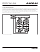
frequency. The maximum TCK clock frequency should be limited to 1/8 the system clock frequency. Figure 11-1 shows a simplified
functional block diagram of the MAXQ7667 TAP and TAP controller.
The TAP provides an independent serial channel to communicate synchronously with the host system. The TMS signal is sampled at
the rising edge of TCK and decoded by the TAP controller to control movement between the TAP states. The TDI input and TDO out-
puts are meaningful once the TAP is in a serial shift state.
The TAP controller block has four working registers that control the operation of the port.
• TAP Debug Register
• TAP System Programming Register
• TAP Instruction Register
• TAP Bypass Register
These registers are accessed through the TAP port only and control the sequencing of the TAP state machine. These registers are not
accessible fr
om the CPU.