
Owner's manual


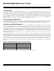


Figure 2-8. DVDDIO Brownout Interrupt Threshold Detection
NOMINAL
DVDDIO (+5.0V)
DVDDIO
BROWNOUT
INTERRUPT
DVDDIO BROWNOUT
INTERRUPT THRESHOLD
RANGE VIOBI[1:0] = 01
VIOBI FLAG CLEARED
IN INTERRUPT HANDLER
VIOLVL
FLAG
+4.79V
+4.30V
GNDIO
VIOBI
FLAG
2.7 Reset Mode
When the MAXQ7665/MAXQ7666 are in reset mode, the enabled system clock oscillator continues running, but no instruction execu-
tion or other system or peripheral operations occur, and all input/output pins return to default states. Once the condition that caused
the reset (whether internal or external) is removed, code execution resumes at address 8000h for all reset types. Some of the reset
sources will also trigger a delaying count of 65,536 clocks (as discussed above) before execution starts.
There are five different sources that can cause the MAXQ7665/MAXQ7666 to enter reset mode. See
Section 2.5
for information on
power-on and brownout reset.
• Power-on reset
• Brownout reset
• Watchdog timer reset
• External reset
• Internal system reset
2.7.1 Watchdog Timer Reset
The MAXQ7665/MAXQ7666 watchdog timer is described in
Section 5
. The watchdog timer is a programmable hardware timer that can
be set to reset the MAXQ7665/MAXQ7666 in the case of a software lockup or other unrecoverable error. Once the watchdog is enabled
in this manner, the processor must refresh the watchdog periodically to avoid a reset. If the processor does not reset the watchdog timer
before it elapses, the watchdog will initiate a reset state. When running at 7.6MHz, the maximum watchdog time period before reset is
approximately 276ms.
If the watchdog resets the MAXQ7665/MAXQ7666, it remains in reset and holds the RESET pin low for four clock cycles. Once the reset
condition has completed, the processor will begin executing program code at address 8000h. When a reset occurs due to a watch-
dog timeout, the watchdog timer reset flag in the WDCN register is set to 1 and can only be cleared by software. User software can
examine this bit following a reset to determine if that reset was caused by a watchdog timeout.
Since the XT bit in the CKCN register and the HFE bit in the OSCC register are cleared to 0 only on power-on reset, it is possible to
exit a watchdog reset with the clock source set to the high frequency crystal oscillator. In this case, execution resumes running from
the RC oscillator, and the switchover to the high-frequency oscillator occurs automatically when the crystal oscillator is ready.
MAXQ7665/MAXQ7666 User’s Guide
2-17
Maxim Integrated