
Owner's manual


SECTION 6: SERIAL I/O MODULE
The MAXQ7665/MAXQ7666 serial I/O module provides access to a universal asynchronous receiver/transmitter (UART) for serial com-
munication with framing error detection. The UART is a full-duplex communication channel capable of supporting asynchronous and
synchronous data transfers. The UART allows the MAXQ7665/MAXQ7666 to conveniently communicate with other RS-232 interface-
enabled devices and can support LIN-bus implementation. Except where explicitly noted, the MAXQ7665 and MAXQ7666 features are
identical.
Features of the MAXQ7665/MAXQ7666 UART include:
• Asynchronous and synchronous data transfer
• Separate transmit and receive interrupts
• Framing error detection
• Baud rate based on system clock or baud-rate generator output
6.1 Architecture
The MAXQ7665/MAXQ7666 UART supports four basic modes of operation and is capable of synchronous and asynchronous com-
munication, with different protocols and baud rates. In the synchronous mode, the microcontroller supplies the clock, and communi-
cation takes place in a half-duplex manner, while the asynchronous mode supports full-duplex operation. Table 6-1 shows the UART
operating modes.
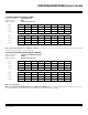
Table 6-1. UART Operation Modes
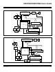
See Figure 6-1 for a simplified functional block diagram of the MAXQ7665/MAXQ7666 UART in synchronous mode. Serial I/O occurs
on the receive pin, which behaves as a bidirectional data line, and the shift clock is provided on the TXD pin. The MAXQ7665/
MAXQ7666 UART in asynchronous mode is shown in Figure 6-2. In asynchronous mode, the UART is a full-duplex communication
channel with a programmable baud-rate generator.
The MAXQ7665/MAXQ7666 UART has a control register (SCON0) and a transmit/receive register (SBUF0). The SBUF0 location pro-
vides access to both transmit and receive registers, where a read is directed to the receive buffer and a write is directed to the trans-
mit buffer. There is a holding buffer that allows the UART to receive an incoming word before software has read the previous one. The
UART baud clock is generated by the baud-rate generator or based directly on the system clock.
MAXQ7665/MAXQ7666 User’s Guide
6-3
UART MODE FUNCTION BAUD CLOCK* DATA BITS START/STOP 9TH BIT FUNCTION MAX BAUD RATE AT 8MHz
0 Synchronous 4 or 12 Clocks 8 None None 2Mbps
1 Asynchronous Baud Generation 8 1 Start, 1 Stop None 250kbps
2 Asynchronous 32 or 64 Clocks 9 1 Start, 1 Stop 0, 1, Parity 250kbps
3 Asynchronous Baud Generation 9 1 Start, 1 Stop 0, 1, Parity 250kbps
*
Use of any system clock-divide modes or power management mode affects the baud clock.
Maxim Integrated