
Datasheet


MAXQ610
16-Bit Microcontroller with Infrared Module
______________________________________________________________________________________ 15
The IRTXPOL bit defines the starting/idle state as well
as the carrier polarity for the IRTX pin. If IRTXPOL = 1,
the IRTX pin is set to a logic-high when the IR timer
module is enabled. If IRTXPOL = 0, the IRTX pin is set
to a logic-low when the IR timer is enabled.
A separate register bit, IR data (IRDATA), is used to
determine whether the carrier generator output is out-
put to the IRTX pin for the next IRMT carrier cycles.
When IRDATA = 1, the carrier waveform (or inversion of
this waveform if IRTXPOL = 1) is output on the IRTX pin
during the next IRMT cycles. When IRDATA = 0, the
idle condition, as defined by IRTXPOL, is output on the
IRTX pin during the next IRMT cycles.
The IR timer acts as a downcounter in transmit mode.
An IR transmission starts when 1) the IREN bit is set to
1 when IRMODE = 1, 2) the IRMODE bit is set to 1
when IREN = 1, or 3) when IREN and IRMODE are both
set to 1 in the same instruction. The IRMT and IRCA
registers, along with the IRDATA and IRTXPOL bits, are
sampled at the beginning of the transmit process and
every time the IR timer value reloads its value. When
the IRV reaches 0000h value, on the next carrier clock,
it does the following:
1) Reloads IRV with IRMT.
2) Samples IRCA, IRDATA, and IRTXPOL.
3) Generates IRTX accordingly.
4) Sets IRIF to 1.
5) Generates an interrupt to the CPU if enabled (IRIE = 1).
To terminate the current transmission, the user can
switch to receive mode (IRMODE = 0) or clear IREN to 0.
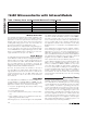
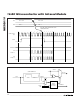
Carrier Modulation Time = IRMT + 1 carrier cycles
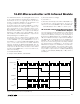
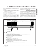
IR Transmit—Independent External Carrier
and Modulator Outputs
The normal transmit mode modulates the carrier based
upon the IRDATA bit. However, the user has the option
to input the modulator (envelope) on an external pin if
desired. If the IRENV[1:0] bits are configured to 01b or
10b, the modulator/envelope is output to the IRTXM pin.
The IRDATA bit is output directly to the IRTXM pin (if
IRTXPOL = 0) on each IRV downcount interval bound-
ary just as if it were being used to internally modulate
the carrier frequency. If IRTXPOL = 1, the inverse of the
IRDATA bit is output to the IRTXM pin on the IRV inter-
val downcount boundaries. The envelope output is illus-
trated in Figure 4. When the envelope mode is enabled,
it is possible to output either the modulated (IRENV[1:0]
= 01b) or unmodulated (IRENV[1:0] = 10b) carrier to
the IRTX pin.
CARRIER OUTPUT
(IRV)
IRDATA
IR INTERRUPT
IRTX
IRTXPOL = 1
IRTX
IRTXPOL = 0
01
0
IRMT = 3
23102310
Figure 3. IR Transmission Waveform (IRCFME = 0)