
Users Guide: MAXQ8913 Supplement User guide


MAXQ Family User’s Guide:
MAXQ8913 Supplement
22-7
22.1.7 I
2
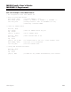
C Slave Address Register (I2CSLA, M1[0Eh])
Bits 15:10: Reserved. Read returns zero.
Bits 9:7: I
2
C Slave Address Register Extended Bits. When 10-bit addressing mode is enabled, these bits contain
the additional address bits (along with bits 6:0) that make up the 10-bit address the I
2
C engine responds to in slave
mode. If 10-bit addressing mode is not enabled, these bits have no function.
Bits 6:0: I
2
C Slave Address Register. These address bits contain the address of the I
2
C device. When a match to
this address is detected, the I
2
C controller automatically acknowledges the transmitter with the I2CACK bit value if
the I
2
C module is enabled (I2CEN = 1). The I2CAMI flag is set to 1 and the I2CMST bit is cleared to 0. An interrupt is
generated to the CPU if enabled.
22.2 I
2
C Code Examples
22.2.1 I
2
C Example 1: Master Mode Transmit
; I2C configured as master, transmit to slave address 08h
; Setup for Master Mode Transmit
move I2CCN, #003h ; I2CEN = 1, I2CMST = 1
call wait_busy ; Polling routine to wait for I2CBUSY to clear
move I2CCN, #043h ; I2CEN = 1, I2CMST = 1, I2CMODE = 0, I2CSTART = 1
call wait_start ; Polling routine to wait for I2CSTART to clear
call wait_busy ; Polling routine to wait for I2CBUSY to clear
move I2CIE.1, #01h ; Enable Transmit Complete Interrupt
move I2CBUF, #008h ; Slave address set to 08h
call wait_tx_complete ; Wait for transmit interrupt
;; Verify ACK from slave
move ACC, I2CST ; Move I2C Status Register to accumulator
and #080h ; Check for NACK bit set in status register
cmp #000h
jump ne, FAIL ; If NACK bit set, handle retransmission, else continue
move I2CBUF, #0aah ; Byte to transmit
call wait_tx_complete ; Wait for transmit interrupt
Bit #
15 14 13 12 11 10 9 8
Name — — — — — — I2CSLA
Reset 0 0 0 0 0 0 1 0
Access r r r r r r rw rw
Bit #
7 6 5 4 3 2 1 0
Name I2CSLA
Reset 0 0 0 0 0 1 0 0
Access rw rw rw rw rw rw rw rw
Maxim Integrated