
Users Guide: MAXQ8913 Supplement User guide


MAXQ Family User’s Guide:
MAXQ8913 Supplement
19-8
19.2.6 ADC Conversion Configuration Registers (ADCFG[0] to ADCFG[7], ADDATA[10h]
to ADDATA[17h])
The eight conversion configuration registers ADCFG[0] to ADCFG[7] provide settings for each individual conversion in
an ADC conversion sequence. As the ADC autoscans, it reads each configuration register in the sequence in turn and
performs a conversion using the settings from that register. The starting and ending configuration registers (inclusive)
in the sequence are given by the SEQSTART and SEQEND bit fields in the ADADDR register.
The number of configuration registers selected by ADADDR also determines the number of conversions performed in
the sequence (one conversion per register selected). The ADCFG registers cannot be written to while a conversion
sequence is in progress (ADCONV = 1).
Bits 15:7: Reserved
Bit 6: ADC Reference Select (ADREF). This bit determines (in conjunction with IREFEN) which reference is used for
this ADC conversion.
0 = AVDD (default) is used as the reference for this conversion.
1 = If IREFEN = 1, the internal reference is used for this conversion; otherwise, the external reference is used.
Bit 5: ADC Sample Acquisition Extension Enable (ADACQEN). This bit determines whether the acquisition time for
this conversion is extended by the number of ADC clock cycles given by ADACQ[3:0].
Bit 4: ADC Data Alignment Select (ADALGN). This bit determines how the ADC sample for this conversion is stored
in the ADBUF register.
0 = The ADC data is stored right-adjusted in bits [11:0] of the ADBUF register. For single-ended conversions, bits
[15:12] are filled with zeros, while for differential conversions bits [15:12] are sign extended from bit 11.
1 = The ADC data is stored left-adjusted in bits [15:4] of the ADBUF register with bits [3:0] zero padded.
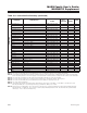
Bit 3: ADC Differential Mode Select (ADDIFF); Bits 2:0: ADC Channel Select (ADCH[2:0]). These four bits control
which channel or pair of channels is used for a given conversion, and whether the conversion is performed in single-
ended or differential mode. In differential mode, since there are only three channel pairs, bit ADCH[2] is ignored.
*Can only be written when ADCONV = 0.
Bit #
15 14 13 12 11 10 9 8
Name — — — — — — — —
Reset 0 0 0 0 0 0 0 0
Access r r r r r r r r
Bit #
7 6 5 4 3 2 1 0
Name — ADREF ADACQEN ADALGN ADDIFF ADCH2 ADCH1 ADCH0
Reset 0 0 0 0 0 0 0 0
Access r rw* rw* rw* rw* rw* rw* rw*
ADDIFF ADCH2 ADCH1 ADCH0 ADC CONVERSION TYPE
0 0 0 0 Single-ended conversion: AIN0 (to AGND)
0 0 0 1 Single-ended conversion: AIN1 (to AGND)
0 0 1 0 Single-ended conversion: AIN2 (to AGND)
0 0 1 1 Single-ended conversion: AIN3 (to AGND)
0 1 0 0 Single-ended conversion: AIN4 (to AGND)
0 1 0 1 Single-ended conversion: AIN5 (to AGND)5
0 1 1 0 Single-ended conversion: AIN6 (temperature sensor)
0 1 1 1 Reserved
Maxim Integrated