
Users Guide: MAXQ8913 Supplement User guide


MAXQ Family User’s Guide:
MAXQ8913 Supplement
2-10
Figure 2-7. External Reset Timing
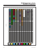
Table 2-3. System Power-Management Registers
2.9 Power-Management Features
The MAXQ8913 provides the following features to assist in power management:
• Divide-by-256 (PMM) mode to reduce current consumption.
• Switchback mode to exit PMM mode automatically when rapid processing is required.
• Ultra-low-power stop mode.
• Selective regulator and brownout detection disable during stop mode.
Table 2-3 shows the system registers and bits used to control power-management features. For more information, see
the register descriptions in this document and in the MAXQ Family User’s Guide.
CLOCK
RST
RESET SAMPLING
INTERNAL RESET
FIRST
INSTRUCTION
FETCH
REGISTER ADDRESS BIT FUNCTION
CKCN M8[0Eh] [1:0]—CD[1:0]
00: System clock = selected clock source divided by 1.
01: System clock = selected clock source divided by 2.
10: System clock = selected clock source divided by 4.
11: System clock = selected clock source divided by 8.
CKCN M8[0Eh] 2—PMME
0: System clock is determined by the settings of CD[1:0].
1: System clock = selected clock source divided by 256.
CKCN M8[0Eh] 3—SWB
When set to 1, enables automatic switchback from PMM (divide-by-256
mode) to normal clock-divide mode under certain conditions.
CKCN M8[0Eh] 4—STOP When set to 1, causes the processor to enter stop mode.
PWCN M0[0Ch] 0—HFXD
0: Enables the high-frequency oscillator.
1: Disables the high-frequency oscillator, allowing an external clock to be
provided at HFXIN.
PWCN M0[0Ch] 6—REGEN
0: Internal regulator is shut down during stop mode.
1: Internal regulator remains powered on during stop mode.
PWCN M0[0Ch] 7—BOD
0: Brownout detection remains enabled during stop mode.
1: Brownout detection is enabled during stop mode.
Maxim Integrated