
Users Guide: MAXQ2010 Supplement User Manual


MAXQ Family User’s Guide:
MAXQ2010 Supplement
21-5
21.2 Timer/Counter B Operation
Timer/Counter B is a 16-bit programmable device that supports clock input prescaling and set/reset/toggle PWM/out-
put control functionality not found on other MAXQ timer implementations. A new register, TBnC, supports certain PWM/
output control functions in some implementations. Another distinguishing characteristic of Timer/Counter B is that its
count ranges from 0000h to the value stored in the 16-bit capture/reload register (TBnR) whereas in other implementa-
tions (e.g., Timer 1), the count ranges from the value in the reload register to FFFFh.
The possible Timer B operating modes and related control bits are shown in Table 21-3. A complete description of each
mode is contained in the subsequent sections. In all modes of operation, the timer is enabled by setting the Timer B
run control bit (TRB) of the Timer B control register (TBnCN.2) to 1. If this bit is cleared to 0 (reset default condition),
no timer activity is possible. When Timer B is operated as a timer (i.e., it counts scaled system clocks), the three bits
TBPS2, TBPS1, and TBPS0 in the timer control register (TBnCN[10:8]) determine the factor by which the active system
clock is divided (prescaled) before being counted by the timer. Other relevant control bits are described in the fol-
lowing mode descriptions. A complete listing of the Timer B registers and bits with their effects on timer operation are
given in Section 21.1: Timer/Counter B Register Descriptions.
21.2.1 Timer B 16-Bit Timer/Counter Mode with Autoreload
The 16-bit autoreload mode of Timer B is established by clearing the CP/RLB bit of the control register (TBnCN.0) to 0.
In this mode, the timer performs a simple 16-bit timer or counter function that is reset to 0000h when a match between
the Timer B count value register (TBnV) and the Timer B capture/reload register (TBnR) occurs. A functional diagram
of autoreload mode is illustrated in Figure 21-1. If the C/TB bit of the timer’s control register (TBnCN.15) is a logic 0,
the timer’s input clock is a prescaled system clock. When C/TB is a logic 1, pulses on the TBA pin are counted. As in
all modes, counting or timing is enabled or disabled with the Timer B run control bit TRB (TBnCN.2)
When enabled (i.e., TRB = 1) in this mode, Timer B begins counting up from the current value contained in the TBnV
register. The TBnV register contents can be read or written any time by software and contains the current value of the
timer. When the value in the TBnV register reaches the value contained in capture/reload register TBnR, the TBF flag is
set to 1. This flag can generate an interrupt if enabled. In addition, upon this match, the timer reloads the TBnV register
with 0000h, and continues timing (or counting) up from that value. The reload value contained in the TBnR register
is preloaded by software. This register cannot be used for the capture function while also performing autoreload, so
these modes are mutually exclusive.
While in autoreload mode, Timer B can also be forced to reload the TBnV register with 0000h using the TBB pin. If the
control bit EXENB (TBnCN.3) is set to 1, a 1-to-0 transition on the TBB pin causes a reload. If the EXENB bit is cleared
to 0, the TBB pin is ignored.
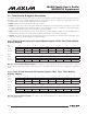
Table 21-3. Timer/Counter B Mode Summary
TIMER B OPERATIONAL
MODE
TBnCN REGISTER BIT SETTINGS
TBCS:TBCR TBOE DCEN EXENB C/TB CP/RLB
OPTIONAL
CONTROL
Autoreload 00 0 0 0 X 0 —
Autoreload Using TBB Pin 00 0 0 1 X 0 —
Capture Using TBB Pin 00 0 0 1 X 1 —
Up/Down Count Using TBB Pin 00 0 1 0 X 0 —
Up-Count PWM/Output Control <>00 X 0 X X 0 —
Up/Down PWM/Output Control <>00 X 1 X X 0 —
— — 0 X X 1 X
Input Clock
= TBA Pin
Clock Output on TBB Pin — 1 X X 0 0 —