
User guide


9-16
MAXQ Family User’s Guide
9.4.2 Timer/Counter 2 Control Register A (T2CNA)
Bit 7: Enable Timer 2 Interrupts (ET2). This bit serves as the local enable for Timer 2 interrupt sources that fall under the TF2 and
TCC2 interrupt flags.
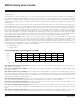
Bit 6: Timer 2 Output Enable 0 (T2OE0). This register bit enables the Timer 2 output function for the external T2P pin. The table below
shows Timer 2 output possibilities for the T2P, T2PB pins.
Bit 5: Timer 2 Polarity Select 0 (T2POL0). When the Timer 2 output function has been enabled (T2OE0 = 1), the polarity select bit
defines the starting logic level for the T2P output waveform. When T2POL0 = 0, the starting state for the T2P output will be logic low.
When T2POL0 = 1, the starting state for the T2P output is logic high. The T2POL0 bit can only be modified when T2OE0 = 0 and takes
effect on the external pin when T2OE0 is set to 1. When the Timer 2 pin is being used as an input (T2OE0 = 0), the polarity select bit
defines which logic level can be used to gate the timer input clock (when CCF[1:0]<>11b). When CCF[1:0] = 11b, T2POL0 defines
which edge can start/stop a single-shot capture and which edge reload can be skipped (if CPRL2 = 1 and G2EN = 1).
Bit 4: T
imer 2 Low Run Enable (TR2L). This bit start/stops the low 8-bit Timer (T2L) when dual 8-bit mode (T2MD = 1) is in effect.
This bit has no ef
fect when T2MD = 0.
0 = Timer 2 Low stopped
1 = Timer 2 Low run
Bit 3: Timer 2 Run Enable (TR2). This bit starts/stop Timer 2. In the dual 8-bit mode of operation, this bit applies only to the T2H
timer/counter. Otherwise, the bit applies to the full 16-bit T2H:T2L timer/counter. When the timer is stopped (TR2 = 0), the timer regis-
ters hold their count. The single-shot bit (SS2) can override and/or delay the effect of the TR2 bit.
0 = Timer 2 stopped
1 = Timer 2 run
Bit 2: Capture and Reload Enable (CPRL2). This bit enables a r
eload (in addition to a capture) on the edge specified by CCF[1:0]
when operating in captur
e/reload mode (C/T2 = 0). If both edges are defined for capture/reload (CCF[1:0] = 11b), enabling the gating
control (G2EN = 1) allows the T2POL0 bit to be used to prevent a reload on one of the edges. If T2POL[0] is 0, no reload on the falling
edge; if T2POL[0] is 1, no reload on the rising edge.
0 = capture on edge(s) specified by CCF[1:0] bits
1 = capture and r
eload on edge(s) specified by CCF[1:0] bits
Bit 1: Single Shot (SS2). This bit is used to automatically override or delay the effect of the TR2 bit setting. The single-shot bit is only
useful in the timer mode of operation (C/T2 = 0) and should not be set to 1 when the counter mode of operation is enabled (C/T2 = 1).
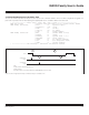
Bit #
7 6 543210
Name ET2 T2OE0 T2POL0 TR2 L TR2 CPRL2 SS2 G2EN
Reset 0 0 0 0 0 0 0 0
Access rw rw rw rw rw rw rw rw
r = read, w = write
T2OE[1:0] T2MD T2P PIN T2PB PIN
00 X Port Data Port Data
01 0 16-Bit PW M Output Port Data
10 0 Port Data 16-Bit PWM Output
11 0 16-Bit PW M Output 16-Bit PW M Output
01 1 8-Bit PWM Output (T2H) Port Data
10 1 Port Data 8-Bit PWM Output (T2L)
11 1 8-Bit PWM Output (T2H) 8-Bit PWM Output (T2L)
Maxim Integrated