
User guide


9-9
MAXQ Family User’s Guide
9.2.5 8-Bit Timer/8-Bit Capture Mode
When the CCF[1:0] bits are configured to a state other than 00b, the edge-capture mode is enabled for the primary timer (T2H). The
secondary timer (T2L) always remains in the timer/compare mode and does not support any capture functionality. The capture con-
trols for the 8-bit mode are identical to those specified for the 16-bit mode, however they apply only to the upper timer, T2H.
One obvious difference is that the secondary timer (T2L), operable only in compare mode, can be used to generate a PWM output with
valid T2OE[1] and T2POL[1] controls, while the primary timer is operating in capture mode.
9.2.6 8-Bit Timer/8-Bit Counter
Just as in the 16-bit mode, setting the C/T2 bit to logic 1 enables the external T2P pin to function as a counter input. The edges that
are counted are determined by the CCF[1:0] bits. The counter mode of operation applies only to the primary timer/counter (T2H). In a
similar fashion to the 16-bit counter mode, when an overflow occurs, an auto-reload of T2RH occurs and the TF2 flag is set. The TCC2
flag is also set on a compare match between the T2H counter and the T2CH compare register (except for the case where T2CH is out-
side the T2RH to 0xFFh counting range. The secondary timer (T2L) always continues to operate in 8-bit compare mode. Just as in the
above split 8-bit timer/8-bit capture mode, this allows the secondary timer (T2L) to function in the PWM output capacity if a T2PB pin
is provided. The T2POL[1] control still applies to the 8-bit T2L PWM output when T2OE[1] = 1.
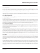
9.2.7 Timer 2 Input Clock Selection
Figure 9-3 shows the Timer 2 clock source. The Timer 2 input clock is selected by the T2CI bit while the clock prescale is determined
by the T2DIV bits in the T2CFG register. Note that when T2CI is configured to 1, the alternate clock source (32kHz) is sampled by the
current system clock selection. The maximum sampleable alternate clock frequency is (system clock/4).
T2CI
32kHz
T2DIV [2:0]
SYSTEM CLOCK
T2CLK
EDGE DETECTION
DIVIDE-BY-N
PRESCALE
Figure 9-3. Timer 2 Clock
Maxim Integrated