
Datasheet


MAX9768
10W Mono Class D Speaker
Amplifier with Volume Control
______________________________________________________________________________________ 15
Hard Current Limit
When the output current exceeds the hard current limit,
2.5A (typ), the MAX9768 disables the outputs and initi-
ates a startup sequence. This startup sequence takes
220ms for the MAX9768 and 15ms for the MAX9768B.
The shutdown and startup sequence is repeated until
the output fault is removed. When in hard current limit,
the output may make a soft clicking sound. The aver-
age supply current is relatively low, as the duty cycle of
the output short is brief. Most applications will not enter
hard current-limit mode unless the output is short cir-
cuited or incorrectly connected.
Thermal Shutdown
When the die temperature exceeds the thermal shut-
down threshold, +150°C (typ), the MAX9768 outputs
are disabled. When the die temperature decreases
below +135°C (typ), normal operation resumes. The
effect of thermal shutdown is an output signal turning
off for approximately 3s in most applications, depend-
ing on the thermal time constant of the audio system.
Most applications should never enter thermal shut-
down. Some of the possible causes of thermal shut-
down are too low of a load impedance, high ambient
temperature, poor PCB layout and assembly, or exces-
sive output overdrive.
Shutdown
The MAX9768 features a shutdown mode that reduces
power consumption and extends battery life. Driving
SHDN low places the device in low-power (0.5µA) shut-
down mode. Connect SHDN to digital high for normal
operation. In shutdown mode, the outputs are high
impedance, SYNCOUT is pulled high, the BIAS voltage
decays to zero, and the common-mode input voltage
decays to zero. The I
2
C register retains its contents
during shutdown.
Undervoltage Lockout (UVLO)
The MAX9768 features an undervoltage lockout protec-
tion that shuts down the device if either of the supplies
are too low. The device will go into shutdown if V
DD
is
less than 2.5V (V
DD
UVLO = 2.5V) or if PV
DD
is less
than 4V (PV
DD
UVLO = 4V).
Mute Function
The MAX9768 features a clickless/popless mute mode.
When the device is muted, the outputs do not stop
switching, only the volume level is muted to the speak-
er. To mute the MAX9768, drive MUTE to logic-high.
MUTE should be held high during system power-up
and power-down to ensure optimum click-and-pop
performance.
Volume Control
The volume control operates from either an analog volt-
age input or through the I
2
C interface. The volume con-
trol has 64 levels, with the lowest setting equal to mute.
To set the device to analog mode, connect ADDR1 and
ADDR2 to GND. In analog mode, SDA/VOL is an ana-
log input for volume control, see the
Functional
Diagram/Typical Application Circuit
. The analog input
range is ratiometric between 0.9 x V
DD
and 0.1 x V
DD
,
where 0.9 x V
DD
= full mute and 0.1 x V
DD
= full volume
(Table 6).
In I
2
C mode, volume control for the speaker is controlled
separately by the command register (Tables 4, 5, 6). See
the
Write Data Format
section for more information
regarding formatting data and tables to set volume levels.
I
2
C Interface
The MAX9768 features an I
2
C 2-wire serial interface
consisting of a serial data line (SDA) and a serial clock
line (SCL). SDA and SCL facilitate communication
between the MAX9768 and the master at clock rates up
to 400kHz. When the MAX9768 is used on an I
2
C bus
with multiple devices, the V
DD
supply must stay pow-
ered on to ensure proper I
2
C bus operation. The mas-
ter, typically a microcontroller, generates SCL and
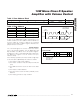
initiates data transfer on the bus. Figure 3 shows the 2-
wire interface timing diagram.
A master device communicates to the MAX9768 by trans-
mitting the proper address followed by the data word.
Each transmit sequence is framed by a START (S) or
REPEATED START (S
r
) condition and a STOP (P) condi-
tion. Each word transmitted over the bus is 8 bits long
and is always followed by an acknowledge clock pulse.
The MAX9768 SDA line operates as both an input and
an open-drain output. A pullup resistor, greater than
500Ω, is required on the SDA bus. The MAX9768 SCL
line operates as an input only. A pullup resistor, greater
than 500Ω, is required on SCL if there are multiple mas-
ters on the bus, or if the master in a single-master sys-
tem has an open-drain SCL output. Series resistors in
line with SDA and SCL are optional. The SCL and SDA
inputs suppress noise spikes to assure proper device
operation even on a noisy bus.