
Datasheet


MAX921–MAX924
Ultra Low-Power,
Single/Dual-Supply Comparators
12 ______________________________________________________________________________________
2. Select R1. The leakage current into INB- is normally
under 1nA, so the current through R1 should
exceed 100nA for the thresholds to be accurate. R1
values up to about 10MΩ can be used, but values in
the 100kΩ to 1MΩ range are usually easier to deal
with. In this example, choose R1 = 294kΩ.
3. Calculate R2 + R3. The overvoltage threshold
should be 5.5V when V
IN
is rising. The design
equation is as follows:
4. Calculate R2. The undervoltage threshold should
be 4.5V when V
IN
is falling. The design equation is
as follows:
5. Calculate R3.
Choose R3 = 1MΩ (1% standard value)
6. Verify the resistor values. The equations are as
follows, evaluated for the above example.
Bar-Graph Level Gauge
The high output source capability of the MAX921 series
is useful for driving LEDs. An example of this is the
simple four-stage level detector shown in Figure 7.
The full-scale threshold (all LEDs on) is given by V
IN
=
(R1 + R2)/R1 volts. The other thresholds are at 3/4 full
scale, 1/2 full scale, and 1/4 full scale. The output
resistors limit the current into the LEDs.
Level Shifter
Figure 8 shows a circuit to shift from bipolar ±5V inputs
to TTL signals. The 10kΩ resistors protect the
comparator inputs, and do not materially affect the
operation of the circuit.
Overvoltage threshold :
V (V V )
(R1 R2 R3)
R1
5.474V.
Undervoltage threshold :
V (V V )
(R1 R2 R3)
(R1 + R2)
4.484V,
where the hysteresis voltage V V
R5
R4
OTH REF H
UTH REF H
H REF
=+×
++
=
=−×
++
=
=×
.
R3 (R2 + R3) R2
.068M 6 k
1.006M
=−
=−
=
119 .
Ω
R2 (R1 + R2 + R3)
(V V )
V
R1
(294k + 1.068M)
(1.182 0.005)
4.5
294k
62.2k
Choose R2 61.9k (1% standard value).
REF H
UTH
=×
−
−
=×
−
−
=
=
Ω
Ω
R2 R3 R1
V
V V
1
294k
5.5
(1.182 0.005)
1
1.068M
OTH
REF H
+=×
+
−
⎛
⎝
⎜
⎞
⎠
⎟
=×
+
−
⎛
⎝
⎜
⎞
⎠
⎟
=Ω
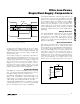
MAX923
INB-
REF
HYST
INA+
V-
V+
OUTA
OUTB
10k
R5
2.4M
R1
R2
R3
UNDERVOLTAGE
POWER GOOD
OVERVOLTAGE
V
IN
V
OTH
= 5.5V
V
UTH
= 4.5V
R4
+5V
Figure 6. Window Detector