
Datasheet


MAX9111/MAX9113
Single/Dual LVDS Line Receivers with
Ultra-Low Pulse Skew in SOT23
_______________________________________________________________________________________ 3
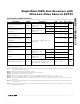
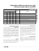
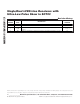
SWITCHING CHARACTERISTICS
(V
CC
= +3.0V to +3.6V, T
A
= T
MIN
to T
MAX
. Typical values are at V
CC
= +3.3V and T
A
= +25°C, unless otherwise noted.) (Notes 4, 5, 6)
Note 1: Maximum and minimum limits over temperature are guaranteed by design and characterization. Devices are production
tested at T
A
= +25°C.
Note 2: Current into the device is defined as positive. Current out of the devices is defined as negative. All voltages are referenced
to ground except V
TH
and V
TL
.
Note 3: Guaranteed by design, not production tested.
Note 4: AC parameters are guaranteed by design and characterization.
Note 5: C
L
includes probe and test jig capacitance.
Note 6: f
MAX
generator output conditions: t
R
= t
F
< 1ns (0 to 100%), 50% duty cycle, V
OH
= 1.3V, V
OL
= 1.1V.
Note 7: t
SKD1
is the magnitude difference of differential propagation delays in a channel. t
SKD1
= |t
PLHD
- t
PHLD
|.
Note 8: t
SKD2
is the magnitude difference of the t
PLHD
or t
PHLD
of one channel and the t
PLHD
or t
PHLD
of the other channel on the
same device.
Note 9: t
SKD3
is the magnitude difference of any differential propagation delays between devices at the same V
CC
and within 5°C
of each other.
Note 10: t
SKD4
, is the magnitude difference of any differential propagation delays between devices operating over the rated supply
and temperature ranges.
PARAMETER SYMBOL CONDITIONS MIN TYP MAX UNITS
T
A
= +85°C 1.0 1.77 2.5
Differential Propagation Delay
High to Low
t
PHLD
C
L
= 15pF, V
ID
=
±200mV, V
CM
= 1.2V
(Figures 1, 2)
T
A
= +125°C 3.0
ns
T
A
= +85°C 1.0 1.68 2.5
Differential Propagation Delay
Low to High
t
PLHD
C
L
= 15pF, V
ID
=
±200mV, V
CM
= 1.2V
(Figures 1, 2)
T
A
= +125°C 3.0
ns
Differential Pulse Skew
|t
PLHD
- t
PHLD
| (Note 7)
t
SKD1
90 300 ps
Differential Channel-to-Channel
Skew; Same Device (MAX9113
only) (Note 8)
t
SKD2
140 400 ps
Differential Part-to-Part Skew
(Note 9)
t
SKD3
1ns
Differential Part-to-Part Skew
(MAX9113 only) (Note 10)
t
SKD4
C
L
= 15pF, V
ID
= ±200mV, V
CM
= 1.2V
(Figures 1, 2)
1.5 ns
T
A
= +85°C 0.6 0.8
Rise Time t
TLH
C
L
= 15pF, V
ID
=
±200mV, V
CM
= 1.2V
(Figures 1, 2)
T
A
= +125°C 1.0
ns
T
A
= +85°C 0.6 0.8
Fall Time t
THL
C
L
= 15pF, V
ID
=
±200mV, V
CM
= 1.2V
(Figures 1, 2)
T
A
= +125°C 1.0
ns
Maximum Operating Frequency f
MAX
All channels switching, C
L
= 15pF,
V
OL
(max) = 0.4V, V
OH
(min) = 2.7V,
40% < duty cycle < 60% (Note 6)
250 300 MHz