
Datasheet


MAX882/MAX883/MAX884
5V/3.3V or Adjustable, Low-Dropout,
Low I
Q
, 200mA Linear Regulators
______________________________________________________________________________________ 13
When operating from sources other than batteries, sup-
ply-noise rejection and transient response can be
improved by increasing the values of the input and out-
put capacitors and employing passive filtering tech-
niques. Do not use power supplies with ripple voltage
exceeding 200mV at 100kHz.
Overshoot and Transient Considerations
The
Typical Operating Characteristics
section shows
power-up, supply, and load-transient response graphs.
On the load-transient graphs, two components of the
output response can be observed: a DC shift from the
output impedance due to the different load currents,
and the transient response. Typical transients for step
changes in the load current from 50mA to 250mA are
200mV. Increasing the output capacitor’s value attenu-
ates transient spikes.
During recovery from shutdown, overshoot is negligible
if the output voltage has been given time to decay ade-
quately. During power-up from V
IN
= 0, overshoot is
typically less than 1% of V
OUT
.
Input-Output (Dropout) Voltage
A regulator’s minimum input-output voltage differential
(or dropout voltage) determines the lowest usable sup-
ply voltage. In battery-powered systems, this deter-
mines the useful end-of-life battery voltage. Because
the MAX882/MAX883/MAX884 use a p-channel MOS-
FET pass transistor, their dropout voltage is a function
of R
DS(ON)
multiplied by the load current (see
Electrical
Characteristics
). Quickly stepping up the input voltage
from the dropout voltage can result in overshoot.
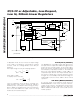
Short-Term Battery Backup
Using the MAX882
Figure 9 illustrates a scheme for implementing battery
backup for 3.3V circuits using the MAX882. When the
supply voltage drops below some user-specified value
based on resistors R1 and R2, the standby function
activates, turning off the MAX882’s output. Under
these conditions, the backup battery supplies power to
the load. Reverse current protection prevents the bat-
tery from draining back through the regulator to the
input.
This application is limited to short-term battery backup
for 3.3V circuits. The current drawn by the MAX882’s
OUT pin at 3.3V during reverse-current protection is
typically 8µA. It should not be used with the MAX883
and MAX884, since the OFF pin is a logic input, and
indeterminate inputs can cause the regulator to turn on
intermittently, draining the battery.
Reverse Battery Protection
Reverse battery protection can be added by including
an inexpensive Schottky diode between the battery
input and the regulator circuit, as shown in Figure 7.
However, the dropout voltage of the regulator will be
increased by the forward voltage drop of the diode. For
example, the forward voltage of a standard 1N5817
Schottky diode is typically 0.29V at 200mA.
BACKUP
BATTERY
MAX882
C
IN
O.1µF
C
OUT
2.2µF
OUTPUT
VOLTAGE
INPUT
VOLTAGE
LBI
SET
STBY
IN
D2
R1
R2
OUT
GND
Figure 9. Short-Term Battery Backup Using the MAX882