
Datasheet


MAX8731A
SMBus Level 2 Battery Charger
with Remote Sense
24 ______________________________________________________________________________________
Compensation
The charge-voltage and charge-current regulation
loops are independent and compensated separately at
the CCV, CCI, and CCS.
CCV Loop Compensation
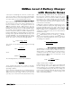
The simplified schematic in Figure 7 is sufficient to
describe the operation of the MAX8731A when the volt-
age loop (CCV) is in control. The required compensa-
tion network is a pole-zero pair formed with C
CV
and
R
CV
. The zero is necessary to compensate the pole
formed by the output capacitor and the load. R
ESR
is
the equivalent series resistance (ESR) of the charger
output capacitor (C
OUT
). R
L
is the equivalent charger
output load, where R
L
= ΔV
BATT
/ ΔI
CHG
. The equiva-
lent output impedance of the GMV amplifier, R
OGMV
, is
greater than 10MΩ. The voltage amplifier transconduc-
tance, GMV = 0.125µA/mV. The DC-DC converter
transconductance is dependent upon the charge-cur-
rent sense resistor RS2:
GM
OUT
=
where A
CSI
= 20V/V, and RS2 = 10mΩ in the typical
application circuits, so GM
OUT
= 5A/V. The loop-trans-
fer function is given by:
The poles and zeros of the voltage loop-transfer function
are listed from lowest frequency to highest frequency in
Table 5.
Near crossover C
CV
is much lower impedance than
R
OGMV
. Since C
CV
is in parallel with R
OGMV
, C
CV
dom-
inates the parallel impedance near crossover.
Additionally, R
CV
is much higher impedance than C
CV
and dominates the series combination of R
CV
and C
CV
,
so near crossover:
RsCR
sC R
R
OGMV CV CV
CV OGMV
CV
×
+×
+×
≅
()
()
1
1
LTF GM R GMV R
sC R sC R
sC R sC R
OUT L OGMV
OUT ESR CV CV
CV OGMV OUT L
=×××
×
+×+×
+× + ×
()()
()()
11
11
1
2ARS
CSI
×
C
CV
C
OUT
R
CV
R
LR
ESR
R
OGMV
CCV
FBS_
GMV
ChargeVoltage( )
GM
OUT
Figure 7. CCV Loop Diagram
NAME EQUATION DESCRIPTION
CCV Pole
Lowest frequency pole created by C
CV
and GMV’s finite output resistance.
CCV Zero
Voltage-loop compensation zero. If this zero is at the same frequency or
lower than the output pole f
P_OUT
, then the loop-transfer function
approximates a single-pole response near the crossover frequency. Choose
C
CV
to place this zero at least 1 decade below crossover to ensure
adequate phase margin.
Output
Pole
Output pole formed with the effective load resistance R
L
and the output
capacitance C
OUT
. R
L
influences the DC gain but does not affect the
stability of the system or the crossover frequency.
Output
Zero
Output ESR Zero. This zero can keep the loop from crossing unity gain if
f
Z_OUT
is less than the desired crossover frequency; therefore, choose a
capacitor with an ESR zero greater than the crossover frequency.
Table 5. CCV Loop Poles and Zeros
f
RC
PCV
OGMV CV
_
=
×
1
2π
f
RC
ZCV
CV CV
_
=
×
1
2π
f
RC
P OUT
L OUT
_
=
×
1
2π
f
RC
P OUT
L OUT
_
=
×
1
2π