
Datasheet


MAX8654
12V, 8A 1.2MHz
Step-Down Regulator
12 ______________________________________________________________________________________
Undervoltage Lockout (UVLO)
The UVLO circuitry inhibits switching when V
IN
or V
VDL
is below 4.20V (typ) or V
VL
is below 3V. Once these
voltages are above the thresholds, UVLO clears and
the soft-start function activates; 100mV of hysteresis is
built in for glitch immunity.
High-Side MOSFET Driver Supply (BST)
The gate-drive voltage for the high-side, n-channel
switch is generated by a flying capacitor boost circuit.
The capacitor between BST and LX is charged from the
VDL supply while the low-side MOSFET is on. When the
low-side MOSFET is switched off, the stored voltage of
the capacitor is stacked above LX to provide the neces-
sary turn-on voltage for the high-side internal MOSFET.
Frequency Select (FREQ)
The switching frequency in fixed-frequency PWM oper-
ation is resistor programmable from 250kHz to 1.2MHz.
Set the switching frequency of the IC with a resistor
(R
FREQ
) from FREQ to GND. R
FREQ
is calculated as:
where f
S
is the desired switching frequency in MHz.
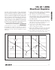
SYNC Function (SYNC, SYNCOUT)
The MAX8654 features a SYNC function that allows the
switching frequency to be synchronized to any external
clock frequency that is higher than the internal clock
frequency. Drive SYNC with a square wave at the
desired synchronization frequency. A rising edge on
SYNC triggers the internal SYNC circuitry. Connect
SYNC to GND to disable the function and operate with
the internal oscillator.
The SYNCOUT output generates a clock signal that is
180° out-of-phase with its internal oscillator, or the sig-
nal applied to SYNC. This allows for another MAX8654
to be synchronized 180° out-of-phase to reduce the
input ripple current.
Power-Good Output (PWRGD)
PWRGD is an open-drain output that goes high imped-
ance once the soft-start ramp has concluded, provided
V
REFIN
is above 0.54V and V
FB
is greater than 90% of
V
REFIN
. PWRGD pulls low when V
FB
is less than 90% of
V
REFIN
and V
REFIN
is less than 0.54V for 48 clock
cycles. PWRGD is low during shutdown, when pulled up
to V
VL
.
Shutdown Mode
Drive EN to GND to shut down the IC and reduce qui-
escent current to 10µA (typ). During shutdown, the out-
puts of the MAX8654 are high impedance. Drive EN
high to enable the MAX8654.
Thermal Protection
Thermal-overload protection limits total power dissipa-
tion in the device. When the junction temperature
exceeds T
J
= +165°C, a thermal sensor forces the
device into shutdown, allowing the die to cool. The ther-
mal sensor turns the device on again after the junction
temperature cools by 20°C, causing a pulsed output
during continuous overload conditions. The soft-start
sequence begins after a thermal-shutdown condition.
Applications Information
VL and VDL Decoupling
To decrease the noise effects due to the high switching
frequency and maximize the output accuracy of the
MAX8654, decouple VDL with a minimum of 2.2µF
ceramic capacitor from VDL to PGND. Also, decouple
VL with a 1µF ceramic capacitor from VL to GND. Place
these capacitors as close to the respective pins as pos-
sible.
Inductor Selection
Choose an inductor with the following equation:
where LIR is the ratio of the inductor ripple current to
average continuous current at the minimum duty cycle.
Choose LIR between 20% to 40% for best performance
and stability.
Use a low-loss inductor with the lowest possible DC
resistance that fits in the allotted dimensions. Powered
iron-ferrite core types are often the best choice for per-
formance. With any core material, the core must be
large enough not to saturate at the peak inductor cur-
rent (I
PEAK
). Calculate I
PEAK
as follows:
I
LIR
xI
PEAK OUT MAX
=+()
()
1
2
L
VxVV
f x V x LIR x I
OUT IN OUT
S IN OUT MAX
=
−()
()
R
f
k
FREQ
S
=×−
⎛
⎝
⎜
⎞
⎠
⎟
Ω52 63
1
005..