
Datasheet


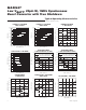


Pin Description
PIN NAME FUNCTION
1 GND Analog Ground. Connect to PG and AGND.
2FB
Voltage Feedback Input. Connect FB to the center of an external feedback network between OUTS
and GND (see the Setting the Output Voltage section). FB regulates to 1.015V (typ).
3ON
Active-High Enable Input. Connect ON to BATT or logic high for normal operation. Connect ON to
GND or logic low for True Shutdown mode.
4, 5 BATT
Supply Voltage Input. Connect to the battery or a supply from 1.5V to 5.5V. Connect two 22µF
ceramic capacitors from BATT to PG.
6, 7 POUT
Power Output. Connect two 22µF ceramic capacitors from POUT to PG (see the Capacitor Selection
section).
8, 9 LX Inductor Connection. LX is high impedance in shutdown.
10, 11 PG Power Ground. Connect to GND and AGND.
12 AGND Analog Ground. Connect to GND and PG.
13 ILIM
n-Channel Current-Limit Control. For the maximum current limit of 3.5A, connect ILIM to GND. For
lower current-limit settings, connect ILIM to a resistor-divider from POUT to GND (see the Setting the
Current Limit section).
14 OUTS IC Power Input. Supplied from the output. Connect OUTS to POUT.
—EP
Exposed Pad. Connect EP to GND. This does not remove the requirement for a proper ground
connection to GND.
MAX8627
Low V
BATT
, 20µA IQ, 1MHz Synchronous
Boost Converter with True Shutdown
7
Maxim Integrated