
Datasheet


MAX817L/M, MAX818L/M, MAX819L/M*
+5V Microprocessor Supervisory Circuits
______________________________________________________________________________________ 13
Watchdog Input Current
The MAX817/MAX818 WDI inputs are internally driven
through a buffer and series resistor from the watchdog
counter (Figure 1). When WDI is left unconnected, the
watchdog timer is serviced within the watchdog timeout
period by a low-high-low pulse from the counter chain.
For minimum watchdog input current (minimum overall
power consumption), leave WDI low for the majority of the
watchdog timeout period, pulsing it low-high-low once
within
7
/8 of the watchdog timeout period to reset the
watchdog timer. If instead WDI is externally driven high for
the majority of the timeout period, up to 150µA can flow
into WDI.
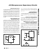
Using a SuperCap™ as a
Backup Power Source
SuperCaps are capacitors with extremely high capaci-
tance values (on the order of 0.47F) for their size. Since
BATT has the same operating voltage range as V
CC
, and
the battery switchover threshold voltages are typically
±30mV centered at V
BATT
, a SuperCap and simple
charging circuit can be used as a backup power source.
Figure 11 shows a SuperCap used as a backup source.
If V
CC
is above the reset threshold and V
BATT
is 0.5V
above V
CC
, current flows to OUT and V
CC
from BATT
until the voltage at BATT is less than 0.5V above V
CC
.
For example, if a SuperCap is connected to BATT
through a diode to V
CC
, and V
CC
quickly changes from
5.4V to 4.9V, the capacitor discharges through OUT
and V
CC
until V
BATT
reaches 5.1V typical. Leakage cur-
rent through the SuperCap charging diode and the
internal power diode eventually discharges the
SuperCap to V
CC
. Also, if V
CC
and V
BATT
start from
0.1V above the reset threshold and power is lost at
V
CC
, the SuperCap on BATT discharges through V
CC
until V
BATT
reaches the reset threshold. Battery-backup
mode is then initiated and the current through V
CC
goes to zero.
Operation Without a
Backup Power Source
The MAX817/MAX818/MAX819 were designed for bat-
tery-backed applications. If a backup battery is not
used, connect V
CC
to OUT, and connect BATT to
ground.
Replacing the Backup Battery
The backup power source can be removed while V
CC
remains valid, without danger of triggering a reset
pulse, if BATT is decoupled with a 0.1µF capacitor to
ground. As long as V
CC
stays above the reset thresh-
old, battery-backup mode cannot be entered.
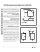
Adding Hysteresis to the Power-Fail
Comparator (MAX817/MAX819)
The power-fail comparator has a typical input hystere-
sis of 4mV. This is sufficient for most applications where
a power-supply line is being monitored through an
external voltage divider (see Monitoring an Additional
Supply).
For additional noise margin, connect a resistor between
PFO and PFI, as shown in Figure 12. Select the ratio of
R1 and R2 such that PFI sees V
PFT
when V
IN
falls to the
Figure 11. Using a SuperCap™ as a Backup Power Source
with a +5V ±10% Supply
SuperCap is a trademark of Baknor Industries.
BATT
V
CC
OUT
RESET
GND
TO STATIC RAM
TO µP
0.1F
MAX817
MAX818
MAX819
+5V
100k
Figure 12. Adding Hysteresis to the Power-Fail Comparator
V
CC
GND
TO µP
PFI
PFO
R1
R2
R3
*OPTIONAL
C1*
V
IN
+5V
R1
+ R2
R2
V
H
= 1.25V
V
TRIP
= 1.25V
+
+
||
||
R2 R3
R1 R2 R3
MAX817
MAX819
PFO
0V
+5V
V
H
V
L
0V
V
TRIP
V
IN
( )
R1
V
L
- 1.25
R3
5
- 1.25
=
R2
1.25
( )