
Datasheet


MAX817L/M, MAX818L/M, MAX819L/M*
+5V Microprocessor Supervisory Circuits
______________________________________________________________________________________ 15
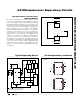
____Pin Configurations (continued)
__________Typical Operating Circuit
WDI
GND
CE OUT
CE IN
1
2
8
7
BATT
RESET
V
CC
OUT
MAX818
DIP/SO/µMAX
TOP VIEW
3
4
6
5
MR
GND
PFO
PFI
1
2
8
7
BATT
RESET
V
CC
OUT
MAX819
DIP/SO/µMAX
3
4
6
5
CE IN*
*CE IN AND CE OUT APPLY TO MAX818 ONLY.
**WDI APPLIES TO MAX817/MAX818 ONLY.
BATT
RESET
I/O
OUT
CMOS
RAM
RESET
WDI**
CE OUT*
0.1µF
0.1µF
0.1µF
GND
MAX817
MAX818
MAX819
V
CC
ADDRESS
DECODE
REAL-
TIME
CLOCK
A0–A15
µP
+5V
Watchdog Software Considerations
(MAX817/MAX818)
To help the watchdog timer monitor software execution
more closely, set and reset the watchdog input at different
points in the program, rather than “pulsing” the watchdog
input high-low-high or low-high-low. This technique avoids
a “stuck” loop, in which the watchdog timer would contin-
ue to be reset within the loop, keeping the watchdog from
timing out. Figure 15 shows an example of a flow diagram
where the I/O driving the watchdog input is set high at the
beginning of the program, set low at the beginning of
every subroutine or loop, then set high again when the
program returns to the beginning. If the program should
“hang” in any subroutine, the problem would quickly be
corrected, since the I/O is continually set low and the
watchdog timer is allowed to time out, triggering a reset or
an interrupt. As described in the Watchdog Input Current
section, this scheme results in higher average WDI input
current than does the method of leaving WDI low for the
majority of the timeout period and periodically pulsing it
low-high-low.
Figure 15. Watchdog Flow Diagram
START
SET
WDI
LOW
SUBROUTINE
OR PROGRAM LOOP,
SET WDI
HIGH
RETURN
END