
Datasheet


MAX817L/M, MAX818L/M, MAX819L/M*
+5V Microprocessor Supervisory Circuits
12 ______________________________________________________________________________________
Backup-Battery Switchover
In a brownout or power failure, it may be necessary to
preserve the contents of RAM. With a backup battery
installed at BATT, the MAX817/MAX818/MAX819 auto-
matically switch RAM to backup power when V
CC
falls.
These devices require two conditions before switching
to battery-backup mode: 1) V
CC
must be below the
reset threshold, and 2) V
CC
must be below V
BATT
.
Table 1 lists the status of the inputs and outputs in bat-
tery-backup mode.
As long as V
CC
exceeds the reset threshold, OUT con-
nects to V
CC
through a 5Ω PMOS power switch. Once
V
CC
falls below the reset threshold, V
CC
or V
BATT
(whichever is higher) switches to OUT. When V
CC
falls
below V
RST
and V
BATT
, BATT switches to OUT through
an 80Ω switch.
When V
CC
exceeds the reset threshold, it is connected to
the substrate, regardless of the voltage applied to BATT
(Figure 10). During this time, the diode (D1) between
BATT and the substrate will conduct current from BATT
to V
CC
if V
BATT
is 0.6V greater than V
CC
. When BATT
connects to OUT, backup mode is activated and the
internal circuitry is powered from the battery (Table 1).
When V
CC
is just below V
BATT
, the current draw from
BATT is typically 6µA. When V
CC
drops to more than 1V
below V
BATT
, the internal switchover comparator shuts
off and the supply current falls to less than 1µA.
__________Applications Information
The MAX817/MAX818/MAX819 are protected for typical
short-circuit conditions of 10sec or less. Shorting OUT
to ground for longer than 10sec destroys the device.
Decouple V
CC
, OUT, and BATT to ground by placing
0.1µF capacitors as close to the device as possible.
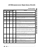
Connected to V
OUT
. Current drawn from
the battery is less than 1µA, as long as
V
CC
< V
BATT
- 0.2V.
V
BATT
Logic low
Disconnected from V
OUT
.V
CC
V
RESET
Logic high. The open-circuit voltage is equal
to V
OUT
.
V
CEOUT
High impedanceV
CEIN
Watchdog timer is disabled.V
WDI
Connected to V
BATT
through an internal 80Ω
PMOS switch.
V
OUT
STATUSSIGNAL
Table 1. Input and Output Status in
Battery-Backup Mode
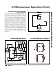
Figure 9. Monitoring an Additional Supply by Connecting
PFO to MR.
MAX819
V2
(RESET)
= 1.25
ADDITIONAL SUPPLY RESET VOLTAGE
R1 + R2
R2
R1
R2
µP
V
CC
V1
V2
RESET
PFI
RESET
MR
PFO
( )
Figure 10. Backup-Battery-Switchover Block Diagram
SW1/SW2
SW3/SW4CONDITION
V
CC
> Reset Threshold Open
Closed
Closed
Open
Open
Closed
V
CC
< Reset Threshold and
V
CC
> V
BATT
V
CC
< Reset Threshold and
V
CC
< V
BATT
RESET THRESHOLD = 4.65V IN MAX81_L
RESET THRESHOLD = 4.4V IN MAX81_M
OUT
D3
SUBSTRATE
D1
D2
SW2
SW1
SW4
SW3
BATT
V
CC
MAX817
MAX818
MAX819