
Datasheet


(V
RT
) is greater than or equal to the minimum IC operat-
ing voltages (V
ICMIN
). The 1% “L” series allows the use
of a 5V ±5% power supply, and guarantees system
operation over worst-case conditions, maximizing the
Power-Supply Guard-Band Range.
T-suffix parts have a minimum reset threshold set to
3.00V, worst case. They are intended for 3.3V systems
(3.33V ±0.26V) with a 7.8% or better power-supply tol-
erance. Typically, the reset threshold (V
RT
) is greater
than or equal to the minimum IC operating voltages
(V
ICMIN
).
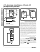
The MAX816 has an adjustable reset threshold, set with
an external resistive divider (Figure 3). The voltage on
the RESET IN pin is monitored, not the voltage on V
CC
.
The RESET IN threshold is 1.700V, and has very high
impedance and 35nA maximum leakage. Calculate the
trip point, V
RT
, as follows:
where V
RT
= the desired reset threshold, V
RIT
is the
RESET IN threshold (1.700V), R1 is the resistor con-
nected between V
RT
and RESET IN, and R2 is the
resistor connected between RESET IN and GND.
Resistors R1 and R2 can have very high values. The
usual procedure is to set R2 to some conveniently high
value (100kΩ, for example) and calculate R1 based on
the desired reset threshold, using the following formula:
The MAX816 can achieve ±1.2% accuracy with 0.1%
resistors.
Watchdog Timer (MAX815)
The watchdog circuit monitors the µP’s activity. If the µP
does not toggle the watchdog input (WDI) within the
watchdog timeout period (t
WP
), WDO goes low (Figure
8). WDO also goes low during reset conditions.
Whenever V
CC
is below the reset threshold, WDO stays
low; however, unlike RESET, WDO does not have a mini-
mum pulse width. As soon as V
CC
rises above the reset
threshold, WDO goes high with no delay (Figure 9).
Typically, WDO is connected to the non-maskable inter-
rupt (NMI) of a µP. When V
CC
drops below the reset
threshold, WDO goes low whether or not the watchdog
timer has timed out (Figure 9). This would normally trig-
ger an NMI interrupt, but RESET goes low simultane-
ously and thus overrides the NMI interrupt.
Connecting WDO to MR enables the watchdog timeout
to generate a reset in the MAX815.
Early Power-Fail Warning
Critical systems often require early warning to indicate
when power is failing. This warning provides time for
the µP to store vital data and take care of any additional
“housekeeping” before the power supply gets too far
out of tolerance for the µP to operate reliably.
Power-Fail Comparator
The power-fail comparator is intended as an undervolt-
age detector to signal a failing power supply. However,
the comparator does not need to be dedicated to this
function, because it is completely separate from the
rest of the circuitry. To build an early-warning circuit for
power failure, connect the PFI pin to a voltage divider
(see Figures 1, 2, and 3). Choose the voltage divider
ratio, so the voltage at PFI falls below V
PFI
just before
the monitored voltage drops out. Use PFO
to interrupt
the µP, so it can prepare for an orderly power-down.
The power-fail input (PFI) is compared to an internal
reference. If the voltage on PFI is less than the power-
fail reference, PFO sinks at least 1.2mA to GND; other-
wise it sources at least 300µA from V
CC
. The reference
is 2.50V in the MAX814/MAX815 with K, L, N suffixes, or
1.70V with the T suffix. It is also 1.70V in the MAX816.
LOW LINE Output (MAX814)
The low-line detector is a separate comparator that
monitors V
CC
with a typical threshold voltage of 60mV
above the normal reset threshold, with 2mV of hystere-
sis (Figure 9). If V
CC
rises faster than 10µs/V, insert a
100pF capacitor from LOW LINE to GND to ensure
proper start-up. For normal operation (V
CC
above the
reset threshold), LOW LINE is pulled to V
CC
. Use LOW
LINE to provide an NMI to the µP when power begins to
fall. In most battery-operated portable systems, reserve
energy in the battery provides ample time to complete
the shutdown routine once the low-line warning is
encountered, and before reset asserts. If the system
must also contend with a more rapid V
CC
fall time—
such as when the main battery is disconnected or a
high-side switch is opened during operation—use
capacitance on the V
CC
line to provide time to execute
the shutdown routine. First, calculate the worst-case
time required for the system to perform its shutdown
routine. Then use the worst-case shutdown time
(t
SHDN
), worst-case load current (I
LOAD
), and minimum
low-line to reset threshold (V
LR
) to calculate the amount
of capacitance required to allow the shutdown routine
to complete before reset is asserted.
C
It
V
HOLD
LOAD SHDN
LR
=
×
RR V V
RT RIT
12 1=×
()
−
[]
/
V
VRR
R
RT
RIT
=
×+
()
12
2
MAX814/MAX815/MAX816
±1% Accuracy, Low-Power, +3V and +5V
µP Supervisory Circuits
______________________________________________________________________________________ 11