
Datasheet


MAX793/MAX794/MAX795
3.0V/3.3V Adjustable Microprocessor
Supervisory Circuits
14 ______________________________________________________________________________________
The power-fail comparator turns off and PFO goes low
when V
CC
falls below V
SW
on power-down. During the
first half of the reset timeout period (t
RP
), PFO is forced
high, irrespective of V
PFI
. At the beginning of the sec-
ond half of t
RP
, the power-fail comparator is enabled
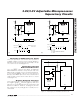
and PFO follows PFI. If the comparator is unused, con-
nect PFI to V
CC
and leave PFO unconnected. PFO can
be connected to MR so that a low voltage on PFI gener-
ates a reset (Figure 12b). In this configuration, when
the monitored voltage causes PFI to fall below V
PFT
,
PFO pulls MR low, causing a reset to be asserted.
Reset remains asserted as long as PFO holds MR low,
and for 200ms after PFO pulls MR high when the moni-
tored supply is above the programmed threshold.
Backup-Battery Switchover
In the event of a brownout or power failure, it may be
necessary to preserve the contents of RAM. With a
backup battery installed at BATT, the devices automati-
cally switch RAM to backup power when V
CC
falls. In
order to allow the backup battery (e.g., a 3.6V lithium
cell) to have a higher voltage than V
CC
, this family of µP
supervisors (designed for 3.3V and 3V systems) does
not always connect BATT to OUT when V
BATT
is
greater than V
CC
. BATT connects to OUT (through a
140Ω switch) either when V
CC
falls below V
SW
and
V
BATT
is greater than V
CC
, or when V
CC
falls below
1.75V (typ) regardless of the BATT voltage.
Switchover at V
SW
ensures that battery-backup mode is
entered before V
OUT
gets too close to the 2.0V mini-
mum required to reliably retain data in most CMOS
RAM, (switchover at higher V
CC
voltages would
decrease backup-battery life). When V
CC
recovers,
switchover is deferred either until V
CC
crosses V
BATT
if
V
BATT
is below V
RST
, or when V
CC
rises above the
reset threshold (V
RST
) if V
BATT
is above V
RST
. This
power-up switchover technique prevents V
CC
from
charging the backup battery through OUT when using
an external transistor driven by BATT ON. OUT con-
nects to V
CC
through a 4Ω (max) PMOS power switch
when V
CC
crosses the reset threshold (Figure 13).
BATT ON (MAX793/MAX794)
BATT ON is high when OUT is connected to BATT.
Although BATT ON can be used as a logic output to
indicate the battery switchover status, it is most often
used as a gate or base drive for an external pass tran-
sistor for high-current applications (see
Driving an
External Switch with BATT ON
in the
Applications
Information
section). When V
CC
exceeds V
RST
on
power-up, BATT ON sinks 3.2mA at 0.4V. In battery-
backup mode, this terminal sources 100µA from BATT.
MAX793
MAX794
V
CC
GND
PFI PFO
R1
R2
V
IN
0V
V
IN
PFO
V
TRIP
V
L
V
PFT
= 1.237V
V
PFH
= 10mV
WHERE
3.0V OR 3.3V
V
TRIP
= R2
+
R1
1
)
(
R2
1
–
R1
V
CC
(V
PFT
+ V
PFH
)
V
L
= R2
+
R1
1
)
(
R2
1
–
R1
V
CC
(V
PFT
)
NOTE: V
TRIP,
V
L
ARE NEGATIVE
V
CC
MAX793
MAX794
V
CC
GND
PFI PFO
R1
R2
PFO
V
TRIP
V
H
3.0V OR 3.3V
V
IN
V
TRIP
=
)
(
R2
R1
+
R2
V
PFT
V
H
=
(V
PFT
+
V
PFH
)
V
CC
V
IN
MR
(b)(a)
)
(
R2
R1
+
R2
Figure 12. Using the Power-Fail Comparator to Monitor an Additional Power Supply: (a) V
IN
Is Negative, (b) V
IN
Is Positive