
Datasheet


MAX770–MAX773
Use an N-channel FET as the power switch when using
the shunt regulator (see
MAX773 Shunt-Regulator
Operation
in the
Detailed Description
). The shunt-regu-
lator current powers the MAX773 and also provides the
FET gate-drive current, which depends largely on the
FET’s total gate charge at V
GS
= 5V. To determine the
shunt-resistor value, first determine the maximum shunt
current required.
I
SHUNT
= I
SUPP
+ I
GATE
See
N-Channel MOSFETs
in the
Power-Transistor
Selection
section to determine I
GATE
.
Determine the shunt-resistor value using the following
equation:
V
IN
(min) - V
SHUNT
(max)
R
SHUNT
(max) = ————————————
I
SHUNT
where V
SHUNT
(max) is 6.3V.
The shunt regulator is not disabled in shutdown
mode, and continues to draw the calculated shunt
current.
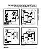
If the calculated shunt regulator current exceeds 20mA,
or if the shunt current exceeds 5mA and less shunt reg-
ulator current is desired, use the circuit of Figure 6 to
provide increased drive and reduced shunt current
when driving N-FETs with large gate capacitances.
Select I
SHUNT
= 3mA. This provides adequate biasing
current for this circuit, although higher shunt currents
can be used.
To prevent the shunt regulator from drawing current in
shutdown mode, place a switch in series with the shunt
resistor.
5V/12V/15V or Adjustable, High-Efficiency,
Low I
Q
, Step-Up DC-DC Controllers
14
______________________________________________________________________________________
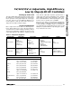
MAX773(N)/MAX773(S)MAX770–MAX773(N)Fixed Output Available
Higher
Lower
GND to V
OUT
2V to 5V (MAX770/MAX771/MAX772),
3V to 5V (MAX773)
MAX770–MAX773(N)
Higher
2V to 16.5V (MAX770/MAX771/MAX772),
(internal feedback resistors)
3V to 16.5V (MAX770/MAX771/MAX772),
(external feedback resistors)
3V to 16.5V (MAX773)
BOOTSTRAPPED*
MAX770/MAX771/MAX772/
MAX773(N)/MAX773(S)
Adjustable Output Available
LowerGate-Drive Capacitive Losses
HigherFET On Resistance
GND to V+Gate Drive
5V to 16.5V
(MAX770/MAX771/MAX772),
5V and up (MAX773)
Normally Recommended Input
Voltage Range
LowerNo-Load Supply Current
3V to 16.5V
(MAX770/MAX771/MAX772),
3V and up (MAX773)
Possible Input Voltage Range
NON-BOOTSTRAPPEDPARAMETER
Table 1. Bootstrapped vs. Non-Bootstrapped Operation
MAX773
CS
FB
SGND
R
SHUNT
N
EXTL
100Ω
V+
C1
C2
0.1µF
V
IN
L1
20µH
NPN
2N2222A
R2
R1
D1
V
OUT
C4
R
SENSE
PNP
2N2907A
3
10
13
12
11
6
EXTH
Figure 6. Increased N-FET Gate Drive when Using the Shunt
Regulator
*MAX773(S) indicates shunt mode; MAX773(N) indicates NOT in shunt mode.