
Datasheet


MAX7490/MAX7491
Dual Universal Switched-Capacitor Filters
______________________________________________________________________________________ 13
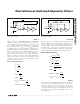
Mode 3
Figure 6 shows the configuration of Mode 3. This mode
is a sampled time (Z transform) equivalent of the classi-
cal 2nd-order state variable filter. In this versatile mode,
the ratio of resistors R2 and R4 can move the center
frequency both above and below the nominal ratio.
Mode 3 is commonly used to make multiple-pole
Chebyshev filters with a single clock frequency. This
mode can also be used to make high-order all-pole
bandpass, lowpass, and highpass filters.
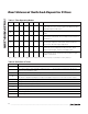
Mode 3 Design Equations
Mode 3A
Figure 7 shows the configuration of Mode 3A. Similar to
Mode 2, this mode adds an external op amp. See
Table 3 for op amp selection ideas. This op amp cre-
ates a highpass notch and lowpass notch by summing
the highpass and lowpass outputs through two external
resistors, R
H
and R
L
. The ratio of resistors R
H
and R
L
adjusts the notch frequency, while R2 and R4 adjust
the bandpass center frequency, since the notch (zero
pair) frequency can be adjusted to both above and
below f
O
. Mode 3A is suitable for both lowpass and
highpass elliptic or Cauer filters. In multipole elliptic fil-
ters, only one external op amp is needed. Use the
inverting input of the internal op amp as the summing
node for all but the final section of the filter.
f
O
f
CLK
R
R
Q
R
R
R
R
H
OHP
R
R
H
OLP
R
R
H
OBP
R
R
=
=
=
=
=
−
−
−
100
2
4
3
2
2
4
2
1
4
1
3
1
Σ
∫ ∫
LP
BPHP
R3
R4
R2
R1
V
IN
C
C
COM
+
-
S
COM
Figure 6. Mode 3, 2nd-Order Section Providing Highpass,
Bandpass, and Lowpass Outputs
Σ
LPBPN/HP
R3
R4
R2
R1
V
IN
C
C
COM
COM
LOWPASS
NOTCH
OUTPUT
+
-
R
H
R
L
R
G
S
COM
Figure 7. Mode 3A, 2nd-Order Filter Providing Highpass Notch or Lowpass Notch Outputs