
Datasheet


If the scan-limit register is set for three digits or less,
individual digit drivers will dissipate excessive amounts of
power. Consequently, the value of the R
SET
resistor must
be adjusted according to the number of digits displayed,
to limit individual digit driver power dissipation. Table 9
lists the number of digits displayed and the corresponding
maximum recommended segment current when the digit
drivers are used.
Display-Test Register
The display-test register operates in two modes: normal
and display test. Display-test mode turns all LEDs on by
overriding, but not altering, all controls and digit registers
(including the shutdown register). In display-test mode, 8
digits are scanned and the duty cycle is 31/32 (15/16 for
MAX7221). Table 10 lists the display-test register format.
No-Op Register
The no-op register is used when cascading MAX7219s
or MAX7221s. Connect all devices’ LOAD/CS inputs
together and connect DOUT to DIN on adjacent devices.
DOUT is a CMOS logic-level output that easily drives
DIN of successively cascaded parts. (Refer to the Serial
Addressing Modes section for detailed information on
serial input/output timing.) For example, if four MAX7219s
are cascaded, then to write to the fourth chip, sent the
desired 16-bit word, followed by three no-op codes (hex
0xX0XX, see Table 2). When LOAD/CS goes high, data is
latched in all devices. The first three chips receive no-op
commands, and the fourth receives the intended data.
Applications Information
Supply Bypassing and Wiring
To minimize power-supply ripple due to the peak digit
driver currents, connect a 10μF electrolytic and a 0.1μF
ceramic capacitor between V+ and GND as close to the
device as possible. The MAX7219/MAX7221 should be
placed in close proximity to the LED display, and connections
should be kept as short as possible to minimize the effects
of wiring inductance and electro-magnetic interference.
Also, both GND pins must be connected to ground.
Selecting R
SET
Resistor and
Using External Drivers
The current per segment is approximately 100 times
the current in ISET. To select R
SET
, see Table 11. The
MAX7219/MAX7221’s maximum recommended segment
current is 40mA. For segment current levels above
these levels, external digit drivers will be needed. In this
application, the MAX7219/MAX7221 serve only as
controllers for other high-current drivers or transistors.
Therefore, to conserve power, use R
SET
= 47kΩ when
using external current sources as segment drivers.
The example in Figure 2 uses the MAX7219/MAX7221’s
segment drivers, a MAX394 single-pole double-throw
analog switch, and external transistors to drive 2.3”
AND2307SLC common-cathode displays. The 5.6V zener
diode has been added in series with the decimal point
LED because the decimal point LED forward voltage is
typically 4.2V. For all other segments the LED forward
voltage is typically 8V. Since external transistors are
used to sink current (DIG 0 and DIG 1 are used as logic
switches), peak segment currents of 45mA are allowed
even though only two digits are displayed. In applications
where the MAX7219/MAX7221’s digit drivers are used
to sink current and fewer than four digits are displayed,
Table 9 specifies the maximum allowable segment
current. R
SET
must be selected accordingly (Table 11).
Refer to the Continuous Power Dissipation section of the
Absolute Maximum Ratings to calculate acceptable limits
for ambient temperature, segment current, and the LED
forward-voltage drop.
Note: The MAX7219/MAX7221 remain in display-test mode
(all LEDs on) until the display-test register is reconfigured
for normal operation.
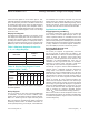
Table 9. Maximum Segment Current for
1-, 2-, or 3-Digit Displays
Table 10. Display-Test Register Format
(Address (Hex) = 0xXF)
MODE
REGISTER DATA
D7 D6 D5 D4 D3 D2 D1 D0
Normal
Operation
X X X X X X X 0
Display Test
Mode
X X X X X X X 1
NUMBER OF DIGITS
DISPLAYED
MAXIMUM SEGMENT
CURRENT
(mA)
1 10
2 20
3 30
MAX7219/MAX7221 Serially Interfaced, 8-Digit LED Display Drivers
www.maximintegrated.com
Maxim Integrated
│
10