
Datasheet


MAX706P/R/S/T, MAX706AP/AR/AS/AT, MAX708R/S/T
+3V Voltage Monitoring, Low-Cost µP
Supervisory Circuits
2 _______________________________________________________________________________________
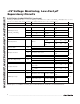
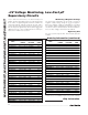
ABSOLUTE MAXIMUM RATINGS
ELECTRICAL CHARACTERISTICS
(MAX70_P/R, MAX706AP/AR: V
CC
= 2.7V to 5.5V; MAX70_S, MAX706AS: V
CC
= 3.0V to 5.5V; MAX70_T, MAX706AT: V
CC
= 3.15V to
5.5V; T
J
= T
A
= T
MIN
to T
MAX
, unless otherwise noted. Typical values are at T
J
= T
A
= +25°C.) (Note 2)
Stresses beyond those listed under “Absolute Maximum Ratings” may cause permanent damage to the device. These are stress ratings only, and functional
operation of the device at these or any other conditions beyond those indicated in the operational sections of the specifications is not implied. Exposure to
absolute maximum rating conditions for extended periods may affect device reliability.
Terminal Voltage (with respect to GND)
V
CC
........................................................................-0.3V to +6V
All Other Inputs (Note 1)..........................-0.3V to (V
CC
+ 0.3V)
Input Current
V
CC
..................................................................................20mA
GND .................................................................................20mA
Output Current (all outputs) ................................................20mA
Continuous Power Dissipation (T
A
= +70°C)
8-Pin CERDIP (derate 8mW/°C above +70°C)..............640mW
8-Pin PDIP (derate 9.1mW/°C above +70°C).............727.3mW
8-Pin SO (derate 5.9mW/°C above +70°C)................470.6mW
8-Pin µMAX (derate 4.5mW/
o
C above +70°C) ..............362mW
Operating Temperature Range
MAX70_C .............................................................0°C to +70°C
MAX70_E ..........................................................-40°C to +85°C
MAX70_M .......................................................-55°C to +125°C
Junction Temperature......................................................+150°C
Storage Temperature Range .............................-65°C to +150°C
Lead Temperature (soldering, 10s) .................................+300°C
Note 1: The input-voltage limits on PFI, WDI, and MR can be exceeded if the input current is less than 10mA.
PARAMETER SYMBOL CONDITIONS MIN TYP MAX UNITS
MAX70_C 1.0 5.5
Supply Voltage Range V
CC
MAX70_E/M 1.2 5.5
V
MAX706_C 90 200
MAX706_E/M 90 300
MAX708_C 50 200
V
CC
< 3.6V
MAX708_E/M 50 300
MAX706_C 135 350
MAX706_E/M 135 500
MAX708_C 65 350
Supply Current I
SUPPLY
V
CC
< 5.5V
MAX708_E/M 65 500
µA
MAX70_P/R, MAX706AP/AR 2.55 2.63 2.70
MAX70_S, MAX706AS 2.85 2.93 3.00
Reset Threshold (Note 3)
(V
CC
Falling)
V
RST
MAX70_T, MAX706AT 3.00 3.08 3.15
V
Reset Threshold Hysteresis
(Note 3)
V
HYS
20 mV
MAX70_P/R, MAX706AP/AR V
CC
= 3.0V 140 200 280
MAX70_S, MAX706AS, V
CC
= 3.3V 140 200 280Reset Pulse Width (Note 3) t
RST
V
CC
= 5V 200
ms
RESET OUTPUT
V
OH
V
RST
(
MAX
)
< V
CC
< 3.6V I
SOURCE
= 500µA
0.8 x
V
CC
V
OL
V
RST
(
MAX
)
< V
CC
< 3.6V I
SINK
= 1.2mA 0.3
V
OH
4.5V < V
CC
< 5.5V
I
RSOURCE
=
800µA
V
CC
-
1.5
V
OL
4.5V < V
CC
< 5.5V I
SINK
= 3.2mA 0.4
MAX70_C V
CC
= 1.0V, I
SINK
= 50µA 0.3
Output-Voltage High
(MAX70_R/S/T)
(MAX706AR/AS/AT)
V
OL
MAX70_E/M: V
CC
= 1.2V, I
SINK
= 100µA 0.3
V