
Datasheet


MAX6964
17-Output LED Driver/GPO with
Intensity Control and Hot-Insertion Protection
12 ______________________________________________________________________________________
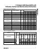
Table 4. Configuration Register (continued)
REGISTER DATA
REGISTER
ADDRESS
CODE
(hex)
D7 D6 D5 D4 D3 D2 D1 D0
CONFIGURATION
R/W
0
BLINK
STATUS
OUTPUT
O16
0
GLOBAL
INTENSITY
BLINK FLIP
BLINK
ENABLE
Write device configuration
0
XX
Read back device configuration
1
0
BLINK O1
O0
0
GBE
Disable global intensity control—intensity
is set by registers 0x10–0x17 for ports O0
through O15 when configured as outputs,
and by D3–D0 of register 0x0E for output
—
XXXXX0 XX
Enable global intensity control—intensity
for all ports configured as outputs is set
by D3–D0 of register 0x0E
—
XXXXX1 XX
O16 output is low (blink is disabled)
—
XXX00XX0
O16 output is high impedance (blink is
disabled)
—
XXX10XX0
O 16 outp ut i s l ow d ur i ng b l i nk p hase 0
—
XXX00XX1
O16 output is high impedance during
blink phase 0
—
XXX10XX1
O 16 outp ut i s l ow d ur i ng b l i nk p hase 1
—
XX0 X 0 XX1
O16 output is high impedance during
blink phase 1
—
XX1 X 0 XX1
Read back BLINK input pin status;
input is low
1
X 0 XXXXXX
Read back BLINK input pin status;
input is high
1
0x0F
X 1 XXXXXX
Table 5. Blink Controls
BLINK ENABLE
FLAG
E
BLINK FLIP
FLAG
B
BLINK INPUT
PIN
BLINK FLIP FLAG
EXOR
BLINK INPUT PIN
BLINK
FUNCTION
OUTPUT REGISTERS
USED
0 X X X Disabled Blink phase 0
0 0 0 Blink phase 0
0 1 1 Blink phase 1
1 0 1 Blink phase 1
1
11 0
Enabled
Blink phase 0
X = Don’t care.
X = Don’t care.