
Datasheet


Adding Hysteresis to the
Power-Fail Comparator
Hysteresis adds a noise margin to the power-fail compar-
ator and prevents repeated triggering of PFO when V
IN
is
near the power-fail comparator trip point. Figure 11 shows
how to add hysteresis to the power-fail comparator. Select
the ratio of R1 and R2 such that PFI sees 1.25V when
V
IN
falls to the desired trip point (V
TRIP
). Resistor R3
adds hysteresis. It will typically be an order of magnitude
greater than R1 or R2. The current through R1 and R2
should be at least 1μA to ensure that the 25nA (max) PFI
input current does not shift the trip point. R3 should be
larger than 10kΩ to prevent it from loading down the PFO
pin. Capacitor C1 adds noise rejection.
Monitoring a Negative Voltage
The power-fail comparator can be used to monitor a
negative supply voltage using Figure 12’s circuit. When
the negative supply is valid, PFO is low. When the nega-
tive supply voltage drops, PFO goes high. This circuit’s
accuracy is affected by the PFI threshold tolerance, the
V
CC
voltage, and resistors R1 and R2.
Backup-Battery Replacement
The backup battery may be disconnected while V
CC
is
above the reset threshold. No precautions are necessary
to avoid spurious reset pulses.
Negative-Going V
CC
Transients
While issuing resets to the μP during power-up, power-
down, and brownout conditions, these supervisors are
relatively immune to short-duration, negative-going V
CC
transients (glitches). It is usually undesirable to reset the
μP when V
CC
experiences only small glitches.
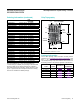
Figure 13 shows maximum transient duration vs. reset-
comparator overdrive, for which reset pulses are not
generated. The graph was produced using negativegoing
V
CC
pulses, starting at 5V and ending below the reset
threshold by the magnitude indicated (reset comparator
overdrive). The graph shows the maximum pulse width a
negative-going V
CC
transient may typically have without
causing a reset pulse to be issued. As the amplitude of
the transient increases (i.e., goes farther below the reset
threshold), the maximum allowable pulse width decreas-
es. Typically, a V
CC
transient that goes 100mV below the
reset threshold and lasts for 40μs or less will not cause a
reset pulse to be issued.
A 100nF bypass capacitor mounted close to the V
CC
pin
provides additional transient immunity.
Connecting a Timing Capacitor at OSC IN
When OSC SEL is connected to ground, OSC IN discon-
nects from its internal 10μA (typ) pullup and is internally
connected to a ±100nA current source. When a capacitor
is connected from OSC IN to ground (to select alternative
reset and watchdog timeout periods), the current source
charges and discharges the timing capacitor to create the
oscillator that controls the reset and watchdog timeout
period. To prevent timing errors or oscillator startup prob-
100
0
10 1000 10000
40
20
80
60
MAX791-16
RESET COMPARATOR OVERDRIVE,
(Reset Threshold Voltage - V
CC
) (mV)
MAXIMUM TRANSIENT DURATION (µs)
100
V
CC
= 5V
T
A
= +25°C
0.1µF CAPACITOR
FROM V
OUT
TO GND
Figure 13. Maximum Transient Duration without Causing a
Reset Pulse vs. Reset Comparator Overdriv
MAX691A/MAX693A/
MAX800L/MAX800M
Microprocessor Supervisory Circuits
www.maximintegrated.com
Maxim Integrated
│
14