
Datasheet


MAX690T/S/R, 704T/S/R, 802T/S/R, 804–806T/S/R
_______________Detailed Description
Reset Output
A microprocessor’s (µP’s) reset input starts the µP in a
known state. These µP supervisory circuits assert reset to
prevent code execution errors during power-up, power-
down, brownout conditions, or a watchdog timeout.
–
R
—
E
—
S
—
E
—
T
–
is guaranteed to be a logic low for 0V < V
CC
<
V
RST
, provided that VBATT is greater than 1V. Without
a backup battery,
–
R
—
E
—
S
—
E
—
T
–
is guaranteed valid for V
CC
> 1V. Once V
CC
exceeds the reset threshold, an
internal timer keeps
–
R
—
E
—
S
—
E
—
T
–
low for the reset timeout
period; after this interval,
–
R
—
E
—
S
—
E
—
T
–
goes high (Figure 2).
If a brownout condition occurs (V
CC
dips below the
reset threshold),
–
R
—
E
—
S
—
E
—
T
–
goes low. Each time
–
R
—
E
—
S
—
E
—
T
–
is asserted, it stays low for the reset timeout period.
Any time V
CC
goes below the reset threshold, the
internal timer restarts.
The watchdog timer can also initiate a reset. See the
Watchdog Input section.
The MAX804_/MAX805_ active-high RESET output is
open drain, and the inverse of the MAX690_/MAX704_/
MAX802_/MAX806_
–
R
—
E
—
S
—
E
—
T
–
output.
Reset Threshold
The MAX690T/MAX704T/MAX805T are intended for
3.3V systems with a ±5% power-supply tolerance and a
10% system tolerance. Except for watchdog faults,
reset will not assert as long as the power supply
remains above 3.15V (3.3V - 5%). Reset is guaranteed
to assert before the power supply falls below 3.0V.
The MAX690S/MAX704S/MAX805S are designed for
3.3V ±10% power supplies. Except for watchdog
faults, they are guaranteed not to assert reset as long
as the supply remains above 3.0V (3.3V - 10%). Reset
is guaranteed to assert before the power supply falls
below 2.85V (V
CC
- 14%).
The MAX690R/MAX704R/MAX805R are optimized for
monitoring 3.0V ±10% power supplies. Reset will not
occur until V
CC
falls below 2.7V (3.0V - 10%), but is
guaranteed to occur before the supply falls below
2.59V (3.0V - 14%).
The MAX802R/S/T, MAX804R/S/T, and MAX806R/S/T
are respectively similar to the MAX690R/S/T,
MAX805R/S/T, and MAX704R/S/T, but with tightened
reset and power-fail threshold tolerances.
3.0V/3.3V Microprocessor Supervisory Circuits
6 _______________________________________________________________________________________
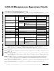
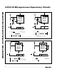
______________________________________________________________Pin Description
1 V
OUT
Supply Output for CMOS RAM. When V
CC
is above the reset threshold, V
OUT
is
connected to V
CC
through a p-channel MOSFET switch. When V
CC
falls below V
SW
and
VBATT, VBATT connects to V
OUT
. Connect to V
CC
if no battery is used.
2 V
CC
Main Supply Input
3 GND Ground
4 PFI
Power-Fail Input. When PFI is less than V
PFT
or when V
CC
falls below V
SW
,
–
P
—
F
—
O
–
goes
low; otherwise,
–
P
—
F
—
O
–
remains high. Connect to ground if unused.
7
–
R
—
E
—
S
—
E
—
T
–
Active-Low Reset Output. Pulses low for 200ms when triggered, and stays low whenever
V
CC
is below the reset threshold or when
–
M
—
R
–
is a logic low. It remains low for 200ms after
either V
CC
rises above the reset threshold, the watchdog triggers a reset, or
–
M
—
R
–
goes
from low to high.
—
–
M
—
R
–
Manual Reset Input. A logic low on
–
M
—
R
–
asserts reset. Reset remains asserted as long as
–
M
—
R
–
is low and for 200ms after
–
M
—
R
–
returns high. This active-low input has an internal
70µA pullup current. It can be driven from a TTL or CMOS logic line, or shorted to ground
with a switch. Leave open if unused.
6 WDI
Watchdog Input. If WDI remains high or low for 1.6s, the internal watchdog timer runs out
and reset is triggered. The internal watchdog timer clears while reset is asserted or when
WDI sees a rising or falling edge. The watchdog function cannot be disabled.
5
–
P
—
F
—
O
–
Power-Fail Output. When PFI is less than V
PFT
, or V
CC
falls below V
SW
,
–
P
—
F
—
O
–
goes low;
otherwise,
–
P
—
F
—
O
–
remains high. Leave open if unused.
8 VBATT
Backup-Battery Input. When V
CC
falls below V
SW
and VBATT, V
OUT
switches from V
CC
to
VBATT. When V
CC
rises above the reset threshold, V
OUT
reconnects to V
CC
. VBATT may
exceed V
CC
. Connect to V
CC
if no battery is used.
— RESET Active-High, Open-Drain Reset Output is the inverse of
–
R
—
E
—
S
—
E
—
T
–
.
NAME FUNCTION
MAX690
MAX802
1
2
PIN
3
4
—
—
6
5
8
7
MAX804
MAX805
1
2
3
4
7
6
—
5
8
—
MAX704
MAX806