
Datasheet


Detailed Description
RESET/RESET Output
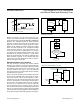
A µP’s reset input starts the µP in a known state. The
MAX6821–MAX6825 µP supervisory circuits assert a
reset to prevent code-execution errors during power-up,
power-down, and brownout conditions. Whenever V
CC
falls below the reset threshold, the reset output asserts
low for RESET and high for RESET. Once V
CC
exceeds
the reset threshold, an internal timer keeps the reset out-
put asserted for the specified reset timeout period (t
RP
);
after this interval, reset output returns to its original state
(see Figure 2).
Manual Reset Input
Many µP-based products require manual reset capabili-
ty, allowing the operator, a test technician, or external
logic circuitry to initiate a reset. On the MAX6821/
MAX6822/MAX6823/MAX6825, a logic low on MR
asserts a reset. Reset remains asserted while MR is
low, and for the timeout period (140ms min) after it
returns high. MR has an internal 50kΩ pullup resistor,
so it can be left open if not used. This input can be dri-
ven with CMOS logic levels or with open-drain/collector
outputs. Connect a normally open momentary switch
from MR to GND to create a manual reset function;
external debounce circuitry is not required. If MR is dri-
ven from long cables or the device is used in a noisy
environment, connect a 0.1µF capacitor from MR to
GND to provide additional noise immunity.
Watchdog Input
In the MAX6821–MAX6824, the watchdog circuit moni-
tors the µP’s activity. If the µP does not toggle (low to
high or high to low) the watchdog input (WDI) within the
watchdog timeout period (1.6s nominal), reset asserts
for the reset timoeout period. The internal 1.6s timer
can be cleared by either a reset pulse or by toggling
WDI. The WDI can detect pulses as short as 50ns.
While reset is asserted, the timer remains cleared and
does not count. As soon as reset is released, the timer
starts counting (see Figure 3).
PIN NUMBERS
PIN
NAME
FUNCTION
MAX6821 MAX6822 MAX6823 MAX6824 MAX6825
1 1 1 1 RESET
Active-Low Open-Drain or Push-Pull Reset Output. RESET
changes from high to low when the V
CC
input drops below the
selected reset threshold, MR is pulled low, or the watchdog triggers
a reset. RESET remains low for the reset timeout period after V
CC
exceeds the device reset threshold, MR goes low to high, or the
watchdog triggers a reset.
1 3 3 RESET
Active-High Push-Pull Reset Output. RESET changes from low to
high when the V
CC
input drops below the selected reset threshold,
MR is pulled low, or the watchdog triggers a reset. RESET remains
high for the reset timeout period after V
CC
exceeds the device
reset threshold, MR goes low to high, or the watchdog triggers a
reset.
2 2 2 2 2 GND Ground
3 3 3 4 MR
Active-Low Manual Reset Input. Internal 50kΩ pullup to V
CC
.
Pull low to force a reset. Reset remains active as long as MR is
low and for the reset timeout period after MR goes high. Leave
unconnected or connect to V
CC
if unused.
4 4 4 4 WDI
Watchdog Input. If WDI remains high or low for longer than the
watchdog timeout period, the internal watchdog timer runs out
and a reset is triggered for the reset timeout period. The internal
watchdog timer clears whenever reset is asserted, the manual
reset is asserted, or WDI sees a rising or falling edge. If WDI is left
unconnected or is connected to a three-stated buffer output, the
watchdog feature is disabled.
5 5 5 5 5 V
CC
Supply Voltage and Input for Reset Threshold Monitor
www.maximintegrated.com
Maxim Integrated
│
5
MAX6821/MAX6825 Low-Voltage SOT23 µP Supervisors
with Manual Reset and Watchdog Timer
Pin Description