
Datasheet


resistors are not required when using the MAX6709/
MAX6714 because hysteresis is built into the device.
MAX6709/MAX6714 hysteresis is typically 0.3% of the
threshold voltage.
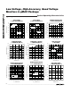
Undervoltage Detection Circuit
The open-drain outputs of the MAX6709/MAX6714 can
be configured to detect an undervoltage condition.
Figure 3 shows a configuration where an LED turns on
when the comparator output is low, indicating an
undervoltage condition.
The MAX6709/MAX6714 can also be used in applica-
tions such as system supervisory monitoring, multivolt-
age level detection, and V
CC
bar graph monitoring
(Figure 4).
Window Detection
A window detector circuit uses two auxiliary inputs in a
configuration such as the one shown in Figure 5.
External resistors R1–R4 set the two threshold voltages
(V
TH1
and V
TH4
) of the window detector circuit. Window
width (∆V
TH
) is the difference between the threshold
voltages (Figure 6).
Adjustable Input
The MAX6709 offers several monitor options with
adjustable reset thresholds. The MAX6714 has three
monitored inputs with adjustable thresholds. The thresh-
old voltage at each adjustable IN_ (PFI_) input is typically
0.62V. To monitor a voltage >0.62V, connect a resistor-
divider network to the circuit as shown in Figure 7.
V
INTH
= 0.62V ✕ (R1 + R2) / R2
MAX6709/MAX6714
Low-Voltage, High-Accuracy Quad, Voltage
Monitors in µMAX Package
_______________________________________________________________________________________ 9
IN1
V
CC
GND
IN2
IN3
IN4
PWRGD1
PWRGD2
PWRGD3
PWRGD4
5V
MAX6709
V1
V2
V3
V4
Figure 3. Quad Undervoltage Detector with LED Indicators
D3
D1
D2
D4
IN1
V
CC
GND
IN2
IN3
IN4
PWRGD1
PWRGD2
PWRGD3
PWRGD4
V
IN
(5V)
5V
MAX6709
Figure 4. V
CC
Bar Graph Monitoring
IN1
V
CC
GND
IN2
IN3
IN4
PWRGD1
PWRGD2
PWRGD3
PWRGD4
5V
MAX6709
OUT
INPUT
R2
R4
R1
R3
V
TH1
=
(
1 +
)
V
REF
R2
R1
V
TH4
=
(
1 +
)
V
REF
R4
R3
V
REF
= 0.62V
Figure 5. Window Detection
PWRGD1
PWRGD4
OUT
V
TH1
V
TH4
∆V
TH
Figure 6. Output Response of Window Detector Circuit