
Datasheet


MAX6698
Status Registers Functions
Status registers 1, 2, and 3 (Tables 8, 9, 10) indicate
which (if any) temperature thresholds have been
exceeded and if there is an open-circuit or short-circuit
fault detected with the external sense junctions. Status
register 1 indicates if the measured temperature has
exceeded the threshold limit set in the ALERT registers
for the local or remote-sensing diodes. Status register 2
indicates if the measured temperature has exceeded
the threshold limit set in the OVERT registers. Status
register 3 indicates if there is a diode fault (open or
short) in any of the remote-sensing channels.
Bits in the alert status register clear by a successful
read, but set again after the next conversion unless the
fault is corrected, either by a drop in the measured tem-
perature or an increase in the threshold temperature.
The ALERT interrupt output follows the status flag bit.
Once the ALERT output is asserted, it can be deassert-
ed by either reading status register 1 or by successfully
responding to an alert response address. In both cases,
the alert is cleared even if the fault condition exists, but
the ALERT output reasserts at the end of the next con-
version. Reading the status 2 register does not clear the
OVERT interrupt output. To eliminate the fault condition,
7-Channel Precision Remote-Diode, Thermistor,
and Local Temperature Monitor
12 ______________________________________________________________________________________
BIT NAME
POR
STATE
FUNCTION
7(MSB) STOP 0
Standby Mode Control Bit. If STOP is set to logic 1, the MAX6698 stops
converting and enters standby mode.
6POR0
Reset Bit. Set to logic 1 to put the device into its power-on state. This bit is self-
clearing.
5 TIMEOUT 0 Timeout Enable Bit. Set to logic 0 to enable SMBus timeout.
4 Fast remote 1 0
Channel 1 Fast Conversion Bit. Set to logic 1 to enable fast conversion of
channel 1.
3
Resistance
cancellation
0
Resistance Cancellation Bit. When set to logic 1, the MAX6698 cancels series
resistance in the channel 1 thermal diode.
2 Reserved 0 —
1 Reserved 0 —
0 Reserved 0 —
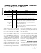
Table 5. Configuration 1 Register
BIT NAME
POR STATE
FUNCTION
7(MSB)
Reserved 0 —
6 Mask Local ALERT 0 Local Alert Mask. Set to logic 1 to mask local channel ALERT.
5
Mask Thermistor 3ALERT
0 Thermistor 3 Alert Mask. Set to logic 1 to mask thermistor 3 ALERT.
4
Mask Thermistor 2ALERT
0 Thermistor 2 Alert Mask. Set to logic 1 to mask thermistor 2 ALERT.
3
Mask Thermistor 1ALERT
0 Thermistor 1 Alert Mask. Set to logic 1 to mask thermistor 1 ALERT.
2
Mask Remote-Diode
3ALERT
0
Remote-Diode 3 Alert Interrupt Mask. Set to logic 1 to mask remote
diode 3 ALERT.
1
Mask Remote-Diode
2ALERT
0
Remote-Diode 2 Alert Interrupt Mask. Set to logic 1 to mask remote
diode 2 ALERT.
0
Mask Remote-Diode
2ALERT
0
Remote-Diode 1 Alert Interrupt Mask. Set to logic 1 to mask remote
diode 1 ALERT.
Table 6. Configuration 2 Register