
Datasheet


MAX6697
cases, the alert is cleared even if the fault condition
exists, but the ALERT output reasserts at the end of the
next conversion. The bits indicating the fault for the
OVERT interrupt output clear only on reading the status
2 register even if the fault conditions still exist. Reading
the status 2 register does not clear the OVERT interrupt
output. To eliminate the fault condition, either the mea-
sured temperature must drop below the temperature
threshold minus the hysteresis value (4°C), or the trip
temperature must be set at least 4°C above the current
temperature.
Applications Information
Remote-Diode Selection
The MAX6697 directly measures the die temperature of
CPUs and other ICs that have on-chip temperature-
sensing diodes (see the
Typical Application Circuit
) or
it can measure the temperature of a discrete diode-
connected transistor.
Effect of Ideality Factor
The accuracy of the remote temperature measurements
depends on the ideality factor (n) of the remote “diode”
(actually a transistor). The MAX6697 is optimized for n
= 1.008. A thermal diode on the substrate of an IC is
normally a pnp with the base and emitter brought out
the collector (diode connection) grounded. DXP_ must
be connected to the anode (emitter) and DXN_ must be
connected to the cathode (base) of this pnp. If a sense
transistor with an ideality factor other than 1.008 is
used, the output data is different from the data obtained
with the optimum ideality factor. Fortunately, the differ-
ence is predictable. Assume a
7-Channel Precision Temperature Monitor
12 ______________________________________________________________________________________
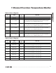
BIT NAME
POR
STATE
FUNCTION
7(MSB) STOP 0
Standby Mode Control Bit. If STOP is set to logic 1, the MAX6697 stops
converting and enters standby mode.
6 POR 0
Reset Bit. Set to logic 1 to put the device into its power-on state. This bit is self-
clearing.
5 TIMEOUT 0 Timeout Enable Bit. Set to logic 0 to enable SMBus timeout.
4 Fast remote 1 0
Channel 1 Fast Conversion Bit. Set to logic 1 to enable fast conversion of
channel 1.
3
Resistance
cancellation
0
Resistance Cancellation Bit. When set to logic 1, the MAX6697 cancels series
resistance in the channel 1 thermal diode.
2 Reserved 0 —
1 Reserved 0 —
0 Reserved 0 —
Table 4. Configuration 1 Register
Table 5. Configuration 2 Register
BIT NAME
POR
STATE
FUNCTION
7(MSB) Reserved 0
6 Mask Local ALERT 0 Local Alert Mask. Set to logic 1 to mask local channel ALERT.
5 Mask ALERT 6 0 Channel 6 Alert Mask. Set to logic 1 to mask channel 6 ALERT.
4 Mask ALERT 5 0 Channel 5 Alert Interrupt Mask. Set to logic 1 to mask channel 5 ALERT.
3 Mask ALERT 4 0 Channel 4 Alert Mask. Set to logic 1 to mask channel 4 ALERT.
2 Mask ALERT 3 0 Channel 3 Alert Interrupt Mask. Set to logic 1 to mask channel 3 ALERT.
1 Mask ALERT 2 0 Channel 2 Alert Mask. Set to logic 1 to mask channel 2 ALERT.
0 Mask ALERT 1 0 Channel 1 Alert Mask. Set to logic 1 to mask channel 1 ALERT.