
Datasheet


1ppm/°C, Low-Noise, +2.5V/+4.096V/+5V
Voltage References
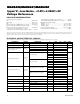
ELECTRICAL CHARACTERISTICS—MAX6350
(V
IN
= +10V, I
OUT
= 0mA, T
A
= T
MIN
to T
MAX
, unless otherwise noted. Typical values are at T
A
= +25°C.)
(Note 4)
V4.999 5.000 5.001V
OUT
Output Voltage +25°C
20 ppmTemperature Hysteresis
C 0.5 1.0
MAX6350
E 0.75 1.5
+25°C
+25°C 10 18
MAX6350C_A
MAX6350E_A
CONDITIONS
30
ppm/
1000hr
8V ≤ V
IN
≤ 10V
Long-Term Stability ∆V
OUT
/t +25°C
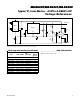
Line Regulation (Note 2)
∆V
OUT
/
∆V
IN
ppm/V
(Figure 1)
To ±0.01% of final value
V836V
IN
Input Voltage Range
+25°C 2.0 3.0
Supply Current I
IN
C, E, M 3.3
mA
Trim-Adjustment Range
UNITSMIN TYP MAXSYMBOLPARAMETER
∆V
OUT
C, E, M ±30 ±50 mV
10 µsTurn-On Settling Time t
ON
+25°C
C, E, M
T
A
C 30
E 35
M 45
C 7
+25°C 25
E 8
10V ≤ V
IN
≤ 36V
M 10
C 16
C 16
E 17
E 17
M
M 29
615
0.1Hz ≤ f ≤ 10Hz
10Hz ≤ f ≤ 1kHz
3.0 µVp-p
Output Noise Voltage (Note 3) e
n
+25°C
2.5 5.0 µV
RMS
Output Voltage Temperature
Coefficient (Note 1)
TCV
OUT
ppm/°C
M 1.0 2.5MAX6350MJA
Note 1: Temperature coefficient is measured by the box method; i.e., the maximum ∆V
OUT
is divided by ∆T x V
OUT
.
Note 2: Line regulation (∆V
OUT
/ (V
OUT
x ∆
VIN
)) and load regulation (∆V
OUT
/ (V
OUT
x ∆I
OUT
)) are measured with pulses and do not
include output voltage changes due to die-temperature changes.
Note 3: Noise specifications are guaranteed by design.
Note 4: Temperature hysteresis is specified at T
A
= +25°C by measuring V
OUT
before and after changing temperature by +25°C,
using the plastic DIP package.
+25°C
Sourcing: 0mA ≤ I
OUT
≤ 15mA
Sinking: -15mA ≤ I
OUT
≤ 0mA
ppm/mA
∆V
OUT
/
∆I
OUT
Load Regulation (Note 2)
MAX6325/MAX6341/MAX6350
4
Maxim Integrated
MAX6325/MAX6341/MAX6350