
Datasheet


MAX6314
68HC11/Bidirectional-Compatible
µP Reset Circuit
6 _______________________________________________________________________________________
MR has an internal 63kΩ pullup resistor, so it can be
left open if not used. Connect a normally open momen-
tary switch from MR to GND to create a manual reset
function; external debounce circuitry is not required. If
MR is driven from long cables or if the device is used in
a noisy environment, connecting a 0.1µF capacitor from
MR to ground provides additional noise immunity.
__________Applications Information
Negative-Going V
CC
Transients
In addition to issuing a reset to the µP during power-up,
power-down, and brownout conditions, these devices
are relatively immune to short-duration negative-going
transients (glitches). The Typical Operating Character-
istics show the Maximum Transient Duration vs. Reset
Threshold Overdrive, for which reset pulses are not
generated. The graph was produced using negative-
going pulses, starting at V
RST
max and ending below
the programmed reset threshold by the magnitude
indicated (reset threshold overdrive). The graph shows
the maximum pulse width that a negative-going V
CC
transient may typically have without causing a reset
pulse to be issued. As the amplitude of the transient
increases (i.e., goes farther below the reset threshold),
the maximum allowable pulse width decreases. A 0.1µF
bypass capacitor mounted close to V
CC
provides addi-
tional transient immunity.
Ensuring a Valid
RESET
Output
Down to V
CC
= 0V
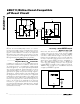
When V
CC
falls below 1V, RESET no longer sinks
current—it becomes an open circuit. Therefore, high-
impedance CMOS-logic inputs connected to RESET
can drift to undetermined voltages. This presents no
problem in most applications, since most µP and other
circuitry is inoperative with V
CC
below 1V. However, in
applications where RESET must be valid down to
V
CC
= 0V, adding a pull-down resistor to RESET will
cause any stray leakage currents to flow to ground,
holding RESET low (Figure 3). R1’s value is not critical;
100kΩ is large enough not to load RESET and small
enough to pull RESET to ground.
Figure 2. MAX6314 Supports Additional Devices on the Reset Bus
4.7kΩ
MR
C
IN
RESET
RESET
CIRCUITRY
V
CC
MAX6314
C
STRAY
68HC11
RESET
CIRCUITRY
C
IN
RESET
V
CC
OTHER DEVICES
C
IN
RESET
Figure 3.
RESET
Valid to V
CC
= Ground Circuit
MAX6314
V
CC
GND
RESET
R1