
Datasheet


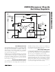


MAX630/MAX4193
CMOS Micropower Step-Up
Switching Regulator
2 _______________________________________________________________________________________
ABSOLUTE MAXIMUM RATINGS
ELECTRICAL CHARACTERISTICS
(+V
S
= +6.0V, T
A
= +25°C, I
C
= 5.0µA, unless otherwise noted.)
Stresses beyond those listed under “Absolute Maximum Ratings” may cause permanent damage to the device. These are stress ratings only, and functional
operation of the device at these or any other conditions beyond those indicated in the operational sections of the specifications is not implied. Exposure to
absolute maximum rating conditions for extended periods may affect device reliability.
Supply Voltage .......................................................................18V
Storage Temperature Range ............................-65°C to +160°C
Lead Temperature (soldering, 10s) .................................+300°C
Operating Temperature Range
MAX630C, MAX4193C........................................0°C to +70°C
MAX630E, MAX4193E .....................................-40°C to +85°C
MAX630M, MAX4193M..................................-55°C to +125°C
Power Dissipation
8-Pin PDIP (derate 6.25mW/°C above +50°C).............468mW
8-Pin SO (derate 5.88mW/°C above +50°C)................441mW
8-Pin CERDIP (derate 8.33mW/°C above +50°C)........833mW
Input Voltage (Pins 1, 2, 6, 7) .....................-0.3V to (+V
S
+ 0.3V)
Output Voltage, L
X
and LBD ..................................................18V
L
X
Output Current ..................................................525mA (Peak)
LBD Output Current ............................................................50mA
MAX630 MAX4193
PARAMETER
SYMBOL
CONDITIONS
MIN TYP MAX MIN TYP MAX
UNITS
Operating 2.0
16.5
Supply Voltage +V
S
Startup 1.9
2.4
16.5
V
Internal Reference Voltage V
REF
1.29 1.31 1.33 1.24 1.31 1.38
V
Switch Current I
SW
V
3
= 400mV 75
150
75
150
mA
Supply Current (at Pin 5) I
S
I
3
= 0mA 70
125
90 µA
Efficiency 85 85 %
Line Regulation
0.5V
0
< V
S
< V
0
(Note 1)
0.08
0.2
0.06
0.5
% V
OUT
Load Regulation
V
S
= +5V, P
LOAD
= 0 to
150mW (Note 1)
0.2
0.5 0.2 0.5
% V
OUT
Operating Frequency Range
F
O
(Note 2) 0.1 40 75 0.1 25 75 kHz
Reference Set Internal
Pulldown Resistance
R
IC
V
6
= V
S
0.5
1.5
10 0.5 1.5 10 MΩ
Reference Set Input Voltage
Threshold
V
IC
0.2
0.8
1.3 0.2 0.8 1.3 V
Switch Current I
SW
V
3
= 1.0V
100 100
mA
Switch Leakage Current I
CO
V
3
= 16.5V
0.01
1.0
0.01
5.0 µA
Supply Current (Shutdown) I
SO
I
C
< 0.01µA
0.01
1.0
0.01
5.0 µA
Low-Battery Bias Current I
LBR
0.01
10
0.01
10 nA
Capacitor Charging Current I
CX
30 30 µA
C
X
+ Threshold Voltage +V
S
- 0.1 +V
S
- 0.1 V
C
X
- Threshold Voltage
0.1
0.1 V
V
FB
Input Bias Current I
FB
0.01
10
0.01
10 nA
Low-Battery Detector Output
Current
I
LBD
V
8
= 0.4V, V
1
= 1.1V
250 600 250 600
µA
Low-Battery Detector Output
Leakage
I
LBDO
V
8
= 16.5V, V
1
= 1.4V
0.01
5.0
0.01
5.0 µA