
Datasheet


MAX5631/MAX5632/MAX5633
16-Bit DACs with 32-Channel
Sample-and-Hold Outputs
4
Maxim Integrated
Note 1: The nominal zero-scale (code = 0) voltage is -4.0535V. The nominal full-scale (code = FFFF hex) voltage is +9.0535V. The
output voltage is limited by the Output Range specification, restricting the useable range of DAC codes. The nominal zero-
scale voltage may be achieved when V
SS
< -4.9V, and the nominal full-scale voltage may be achieved when V
DD
> +11.5V.
Note 2: Gain is calculated from measurements
for voltages V
DD
= 10V and V
SS
= -4V at codes C000 hex and 4F2C hex,
for voltages V
DD
= 11.6V and V
SS
= -2.9V at codes FFFF hex and 252E hex,
for voltages V
DD
= 9.25V and V
SS
= -5.25V at codes D4F6 hex and 0 hex, and
for voltages V
DD
= 8.55V and V
SS
= -2.75V at codes C74A hex and 281C hex.
Note 3: Steady-state change in any output with an 8V change in an adjacent output.
Note 4: Settling during the first update for an 8V step. The output will settle to within the linearity specification on subsequent
updates. Tested with an external sequencer clock frequency of 480kHz.
Note 5: External clock mode with the external clock not toggling.
Note 6: The output voltage is the sum of the DAC output and the voltage at GS. GS gain is measured at 4F2C hex.
Note 7: The sequencer runs at f
SEQ
= f
ECLK
/4. Maximum speed is limited by settling of the DAC and SHAs. Minimum speed is
limited by acceptable droop and update time after a Burst Mode Update.
Note 8: V
DD
rise to CS low = 500µs maximum.
Note 9: Guaranteed by gain-error test.
Note 10: The serial interface is inactive. V
IH
= V
LOGIC
, V
IL
= 0V.
Note 11: The serial interface is active. V
IH
= V
LOGIC
, V
IL
= 0V.
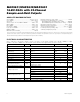
ELECTRICAL CHARACTERISTICS (continued)
(V
DD
= +10V, V
SS
= -4V, V
LOGIC
= V
LDAC
= V
LSHA
= +5V, V
REF
= +2.5V, V
AGND
= V
DGND
= V
GS
= 0V, R
L
≥ 10MΩ, C
L
= 50pF,
CLKSEL = +5V, f
ECLK
= 400kHz, T
A
= T
MIN
to T
MAX
, unless otherwise noted. Typical values are at T
A
= +25°C.)
PARAMETER
SYMBOL
CONDITIONS
MIN
TYP
MAX
UNITS
SCLK High to CS High Hold Time
t
CSH1
0ns
DIN to SCLK High Setup Time t
DS
15 ns
DIN to SCLK High Hold Time t
DH
0ns
RST to CS Low (Note 8) 500 µs
POWER SUPPLIES
Positive Supply Voltage V
DD
(Note 9)
8.55
10 11.6 V
Negative Supply Voltage V
SS
(Note 9)
-5.25
-4
-2.75
V
Supply Difference V
DD
- V
SS
(Note 9) 14.5 V
Logic Supply Voltage
V
LOGIC
,
V
LDAC
,
V
LSHA
4.75
5 5.25 V
Positive Supply Current I
DD
32 42
mA
Negative Supply Current I
SS
32 40
mA
(Note 10) 1 1.5
Logic Supply Current
I
LOGIC
f
SCLK
= 20MHz (Note 11) 2 3
mA