
Datasheet


MAX520/MAX521
Quad/Octal, 2-Wire Serial 8-Bit DACs
with Rail-to-Rail Outputs
14 ______________________________________________________________________________________
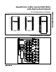
Early Stop Conditions
The addressed device recognizes a STOP condition at
any point in a transmission. If the STOP occurs during a
command byte, all previous uninterrupted command
and output byte pairs are accepted, the interrupted
command byte is ignored, and the transmission ends
(Figure 13a). If the STOP occurs during an output byte,
all previous uninterrupted command and output byte
pairs are accepted, the final command byte
’
s PD and
RST bits are accepted, the interrupted output byte is
ignored, and the transmission ends (Figure 13b).
Analog Section
DAC Operation
The MAX520 contains four matched voltage-output
DACs, and the MAX521 contains eight. The DACs are
inverted R-2R ladder networks that convert 8-bit digital
words into equivalent analog output voltages in propor-
tion to the applied reference voltages. For both
devices, DAC0–DAC3 each have separate reference
inputs, while the MAX521’s DAC4–DAC7 all share a
common reference input. Figure 14 shows a simplified
diagram of one DAC.
Reference Inputs
The MAX520/MAX521 can be used for multiplying appli-
cations. The reference accepts a 0V to V
DD
voltage,
both DC and AC signals. The voltage at each REF input
sets the full-scale output voltage for its respective
DAC(s). The reference voltage must be positive. The
DAC’s input impedance is code dependent, with the
lowest value occurring when the input code is 55 hex or
0101 0101, and the maximum value occurring when the
input code is 00 hex. Since the REF input resistance
( )
( )
( )
SDA
0
START
CONDITION
ADDRESS BYTE
(DEVICE 0)
ACK
10100000 0
0
00000001 0101001001
REPEATED START
CONDITION
STOP
CONDITION
COMMAND BYTE
ADDRESSING DAC1
COMMAND BYTE
(ADDRESSING DAC2)
ACK
OUTPUT BYTE
(FULL SCALE)
ACK
ADDRESS BYTE
(DEVICE 1)
ACK
DEVICE 0's
DAC1 INPUT LATCH
SET TO FULL SCALE
DEVICE 1's
DAC2 INPUT LATCH
SET TO FULL SCALE
SDA
ACK ACK
OUTPUT BYTE
(FULL SCALE)
ONLY DEVICE 1's DAC2 OUTPUT LATCH SET TO FULL
SCALE. DEVICE 0's OUTPUT LATCHES UNCHANGED.
1111 111
000000 00 0111111 111
Figure 12. Repeated START Conditions
( )
SDA
00
START
CONDITION
ADDRESS BYTE ACK
1 1 AD1 AD0 0 0 0 0 0011
(RST) (PD)
(PD)
EARLY
STOP CONDITION
INTERRUPTED
COMMAND BYTE
MAX520/MAX521's STATES
REMAIN UNCHANGED
( )
SDA
0
START
CONDITION
ADDRESS BYTE ACK
101 AD1AD000000 000011100RST 1
COMMAND BYTE
(POWER DOWN)
ACK
INTERRUPTED
OUTPUT BYTE
(a)
(b)
MAX520/MAX521 POWER DOWN;
INPUT LATCHES UNCHANGED IF
RST = 0, DAC OUTPUTS RESET IF
RST = 1.
EARLY
STOP CONDITION
0 OR AD2
0 OR AD2
Figure 13. Early STOP Conditions