
Datasheet


MAX5060/MAX5061
0.6V to 5.5V Output, Parallelable,
Average-Current-Mode DC-DC Controllers
______________________________________________________________________________________ 17
Internal Oscillator
The internal oscillator generates a clock with the fre-
quency proportional to the inverse of R
T
. The oscillator
frequency is adjustable from 125kHz to 1.5MHz with
better than 8% accuracy using a single resistor con-
nected from RT/SYNC to SGND (MAX5060) and from
RT/SYNC/EN to SGND (MAX5061). The frequency accu-
racy avoids the over-design, size, and cost of passive
filter components like inductors and capacitors. Use the
following equation to calculate the oscillator frequency:
for 120kΩ≤R
T
≤ 500kΩ:
for 40kΩ≤R
T
≤ 120kΩ:
The oscillator also generates a 2V
P-P
voltage-ramp sig-
nal for the PWM comparator and a 180° out-of-phase
clock signal for CLKOUT (MAX5060) to drive a second
DC-DC converter out-of-phase.
Synchronization
The MAX5060/MAX5061 can be easily synchronized by
connecting an external clock to RT/SYNC (MAX5060) or
RT/SYNC/EN (MAX5061). If an external clock is pre-
sent, then the internal oscillator is disabled and the
external clock is used to run the MAX5060/MAX5061. If
the external clock is removed, the absence of clock for
32µs is detected and the circuit starts switching from
the internal oscillator. Pulling RT/SYNC on the MAX5060
or RT/SYNC/EN on the MAX5061 to ground for at least
50µs disables the converter.
Use an open-collector transistor to synchronize the
MAX5060/MAX5061 with the external system clock (see
Figures 1 and 2).
R
f
T
SW
.
=
×640 10
10
R
f
T
SW
.
=
×625 10
10
DRIVE
V
IN
V
OUT
C
OUT
V
REF
+ V
CM
R
F
*
*R
F
AND R
IN
ARE EXTERNAL.
C
CFF
C
CF
I
L
R
CF
CSN
CSP
CLP
R
S
LOAD
CPWM
CEA
VEA
DIFF
AMP
SENSE+
SENSE-
CA
R
IN
*
MAX5060
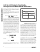
Figure 5. MAX5060 Control Loop