
Datasheet


MAX5054–MAX5057
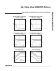
4A, 20ns, Dual MOSFET Drivers
8 _______________________________________________________________________________________
Pin Descriptions
PIN NAME FUNCTION
1 INA- Inverting Logic-Input Terminal for Driver A. Connect to GND when not used.
2 INB- Inverting Logic-Input Terminal for Driver B. Connect to GND when not used.
3 GND Ground
4 OUTB Driver B Output. Sources or sinks current for channel B to turn the external MOSFET on or off.
5V
DD
Power Supply. Bypass to GND with one or more 0.1µF ceramic capacitors.
6 OUTA Driver A Output. Sources or sinks current for channel A to turn the external MOSFET on or off.
7 INB+ Noninverting Logic-Input Terminal for Driver B. Connect to V
DD
when not used.
8 INA+ Noninverting Logic-Input Terminal for Driver A. Connect to V
DD
when not used.
—EP
Exposed Pad. Internally connected to GND. Do not use the exposed pad as the only electrical
ground connection.
PIN
MAX5055 MAX5056 MAX5057
NAME FUNCTION
1, 8 1, 8 1, 8 N.C. No Connection. Not internally connected.
2 — 2 INA- Inverting Logic-Input Terminal for Driver A. Connect to GND if not used.
3 3 3 GND Ground
4 — — INB- Inverting Logic-Input Terminal for Driver B. Connect to GND if not used.
5 5 5 OUTB
Driver B Output. Sources or sinks current for channel B to turn the external
MOSFET on or off.
666V
DD
Power Supply. Bypass to GND with one or more 0.1µF ceramic capacitors.
7 7 7 OUTA
Driver A Output. Sources or sinks current for channel A to turn the external
MOSFET on or off.
— 4 4 INB+ Noninverting Logic-Input Terminal for Driver B. Connect to V
DD
if not used.
— 2 — INA+ Noninverting Logic-Input Terminal for Driver A. Connect to V
DD
if not used.
———EP
Exposed Pad. Internally connected to GND. Do not use the exposed pad as
the only electrical ground connection.
MAX5054
MAX5055/MAX5056/MAX5057