
Datasheet


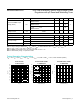


EN and HOLD. Figure 3 shows the timing diagram for the
enable and hold functions. Connecting HOLD to OUT or
floating HOLD allows the EN input to act as a standard
ON/OFF switch for the regulator output.
Thermal Protection
When the junction temperature exceeds T
J
= +150°C, an
internal thermal sensor signals the shutdown logic that
turns off the pass transistor and allows the IC to cool.
The thermal sensor turns the pass transistor on again
after the IC’s junction temperature cools by 20°C, result-
ing in a cycled output during continuous thermal-overload
conditions. Thermal protection protects the MAX5023/
MAX5024 in the event of fault conditions. For continuous
operation, do not exceed the absolute maximum junction
temperature rating of T
J
= +150°C.
Applications Information
Output Voltage Selection (MAX5024 only)
The MAX5024 features Dual Mode™ operation: it oper-
ates in either a preset voltage mode or an adjustable
mode. In preset voltage mode, internal trimmed feedback
resistors set the MAX5024’s internal linear regulator to
+3.3V or +5V (see the Selector Guide).
Figure 3. Enable and Hold Behavior
Dual Mode is a trademark of Maxim Integrated Products, Inc.
V
RESET
V
OUT
V
HOLD
0.2V
200ms
V
TH
>10µs>10µs
1)
2)
3)
4)
6)
7)
8)
9)
5)
V
OUT (NOM)
V
HOLD, HOLD
V
HOLD, REL
V
EN, OFF
V
EN, ON
1) ENABLE ACTIVE
2) HOLD INACTIVE, PULLED UP BY V
OUT
3) POWER-ON RESET
4) HOLD ACTIVE, CLAMPED TO GND BY EXTERNAL µP
5) ENABLE INACTIVE, CLAMPED BY INT, PULLDOWN RESISTOR
6) PULSE WIDTH SMALLER THAN 10µs
7) HOLD INACTIVE, RELEASED BY µP
8) REGULATOR OUTPUT SHUTDOWN
9) OUTPUT-LOW RESET
V
EN
V
IN
MAX5023/MAX5024 65V, Low-Quiescent-Current, High-Voltage Linear
Regulators with μP Reset and Watchdog Timer
www.maximintegrated.com
Maxim Integrated
│
10