
Datasheet


the MAX4823 device. If the address A0…….A7 is not
00h or 01h, then the outputs and the PSAVE configura-
tion register are not updated. The address is stored in
the shift register only.
While CS is low, the OUT_ outputs always remain in their
previous state. For the MAX4823, drive CS high after 8
bits of data have been shifted in to update the output
state of the MAX4823, and to further inhibit data from
entering the shift register. For the MAX4822, drive CS high
after 16 bits of data have been shifted in to update the
output state of the MAX4822, and to further inhibit data
from entering the shift register. When CS is high, transi-
tions at DIN and SCLK have no effect on the output, and
the first input bit A7 (or D7) is present at DOUT.
For the MAX4822, if the number of data bits entered
while CS is low is greater or less than 16, the shift regis-
ter contains only the last 16 bits, regardless of when
they were entered. For the MAX4823, if the number of
data bits entered while CS is low is greater or less than
8, the shift register contains only the last 8 data bits,
regardless of when they were entered.
Parallel Interface (MAX4824/MAX4825)
The parallel interface consists of 3 address bits (A0,
A1, A2) and one level selector bit (LVL). The address
bits determine which output is updated, and the level
bit determines whether the addressed output is
switched on (LVL = high) or off (LVL = low). When CS is
high, the address and level bits have no effect on the
state of the outputs. Driving CS from low to high latches
MAX4822–MAX4825
+3.3V/+5V, 8-Channel Relay Drivers with Fast
Recovery Time and Power-Save Mode
______________________________________________________________________________________ 11
SCLK
DIN
DOUT
t
CSS
t
CL
t
CH
t
CSW
t
CSH
t
DO
t
ON
,
t
OFF
t
DS
t
DH
D7
D6
D1
D0
CS
OUT_
Figure 4. 3-Wire Serial-Interface Timing Diagram
A2 A1 A0 OUTPUT
Low Low Low OUT1
Low Low High OUT2
Low High Low OUT3
Low High High OUT4
High Low Low OUT5
High Low High OUT6
High High Low OUT7
High High High OUT8
Figure 3. Register Address Map for MAX4824/MAX4825
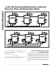
MSB
LSB
D
7
D
6
D
5
D
4
D
3
D
2
D
1
D
0
OUT
8
OUT
7
OUT
6
OUT
5
OUT
4
OUT
3
OUT
2
OUT
1
Note: Setting D
N
to logic 1 turns on output OUT
N+1
. Setting
D
N
to logic 0 turns off output OUT
N+1
.
Example: Setting the D
2
= 1 turns OUT
3
on.
Figure 2. 8-Bit Register Map for MAX4823