9-2522; Rev 3; 2/05 High-Speed, Low-Voltage, 0.7Ω CMOS Analog Switches/Multiplexers Features The MAX4781/MAX4782/MAX4783 are high-speed, low-voltage, low on-resistance, CMOS analog multiplexers/switches configured as an 8-channel multiplexer (MAX4781), two 4-channel multiplexers (MAX4782), and three single-pole/double-throw (SPDT) switches (MAX4783). These devices operate with a +1.6V to +3.6V single supply. When powered from a +3V supply, MAX4781/ MAX4782/MAX4783 feature a 0.
MAX4781/MAX4782/MAX4783 High-Speed, Low-Voltage, 0.7Ω CMOS Analog Switches/Multiplexers ABSOLUTE MAXIMUM RATINGS Voltages Referenced to GND VCC, A, B, C, and ENABLE ...............................-0.3V to +4.6V Voltage at Any Other Terminal (Note 1)...................................................-0.3V to (VCC + 0.3V) Continuous Current into A, B, C, ENABLE........................±10mA Continuous Current into X, Y, Z, X_, Y_, Z_ ....................
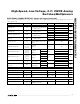
High-Speed, Low-Voltage, 0.7Ω CMOS Analog Switches/Multiplexers (VCC = +2.7V to +3.6V, GND = 0, VIH = 1.4V, VIL = 0.5V, TA = TMIN to TMAX, unless otherwise noted. Typical values are at TA = +25°C.) (Notes 2, 3) PARAMETER SYMBOL CONDITIONS TA TMIN to TMAX MIN TYP MAX UNITS SWITCH DYNAMIC CHARACTERISTICS +25°C 11 25 Turn-On Time tON VX_, VY_, VZ_ = 1.5V; RL = 50Ω; CL = 35pF; Figure 1 Turn-Off Time tOFF VX_, VY_, VZ_ = 1.
MAX4781/MAX4782/MAX4783 High-Speed, Low-Voltage, 0.7Ω CMOS Analog Switches/Multiplexers ELECTRICAL CHARACTERISTICS—Single +1.8V Supply (VCC = +1.8V, GND = 0, VIH = 1V, VIL = 0.4V, TA = TMIN to TMAX, unless otherwise noted. Typical values are at TA = +25°C.) (Notes 2, 3) PARAMETER SYMBOL CONDITIONS TA MIN TYP MAX UNITS VCC V ANALOG SWITCH Analog Signal Range On-Resistance (Note 4) On-Resistance Match Between Channels (Notes 4, 5) VX_, VY_ , VZ_, VX, VY, VZ 0 RON VCC = 1.
High-Speed, Low-Voltage, 0.7Ω CMOS Analog Switches/Multiplexers ON-RESISTANCE vs. VX, VY, VZ, AND TEMPERATURE VCC = 1.8V 0.8 VCC = 3.6V ON VCC = 2.0V 1.2 VCC = 2.5V 0.6 0.5 TA = -40°C 100 OFF 10 0.3 VCC = 3.0V 0.8 TA = +25°C 0.4 VCC = 2.7V 1.0 IX, IY, IZ (pA) 0.7 1.4 RON (Ω) 0.2 0.6 VCC = 3.3V 0.1 VCC = 3.6V VCC = 3.0V 0 0.4 0.5 1.0 1.5 2.0 3.0 2.5 -40 10 35 60 VX, VY, VZ (V) TEMPERATURE (°C) CHARGE INJECTION vs. VX, VY, VZ SUPPLY CURRENT vs.
Typical Operating Characteristics (continued) (GND = 0, TA = +25°C, unless otherwise noted.) TOTAL HARMONIC DISTORTION vs. FREQUENCY FREQUENCY RESPONSE 0.07 ON-RESPONSE -10 MAX4781 toc10 0.08 MAX4781 toc09 VCC = 3V 10 0.06 -30 THD (%) RESPONSE (dB) MAX4781/MAX4782/MAX4783 High-Speed, Low-Voltage, 0.7Ω CMOS Analog Switches/Multiplexers -50 0.05 CROSSTALK 0.04 -70 0.03 -90 OFF-ISOLATION -110 VCC = 3V 0.
High-Speed, Low-Voltage, 0.7Ω CMOS Analog Switches/Multiplexers PIN NAME TSSOP THIN QFN 1, 5, 2, 4 15, 3, 16, 2 Y0–Y3 3 1 Y 6 4 ENABLE FUNCTION Analog Switch Y Inputs Y0–Y3 Analog Switch Y Output Digital Enable Input. Normally connect to GND. Drive to logic high to set all switches off. 7 5 N.C. No Connection. Not internally connected.
MAX4781/MAX4782/MAX4783 High-Speed, Low-Voltage, 0.7Ω CMOS Analog Switches/Multiplexers Applications Information Power-Supply Considerations Overview The MAX4781/MAX4782/MAX4783 construction is typical of most CMOS analog switches. There are two supply inputs: VCC and GND. VCC and GND drive the internal CMOS switches and set the limits of the analog voltage on any switch. Internal reverse ESD-protection diodes are connected between each analog signal input and both VCC and GND.
High-Speed, Low-Voltage, 0.7Ω CMOS Analog Switches/Multiplexers MAX4781/MAX4782/MAX4783 Table 1.
High-Speed, Low-Voltage, 0.
High-Speed, Low-Voltage, 0.
High-Speed, Low-Voltage, 0.7Ω CMOS Analog Switches/Multiplexers MAX4781/MAX4782/MAX4783 Test Circuits/Timing Diagrams (continued) VCC VCC VA, VB, VC VA, VB VCC A X0–X7 VCC A VCC B B X0–X3, Y0–Y3 VCC C MAX4782 MAX4781 ENABLE VOUT X GND ENABLE VOUT X, Y GND 35pF 35pF 50Ω 50Ω VCC VCC VA, VB, VC V+ X0, X1, Y0, Y1, Z0, Z1 A B VA, VB, VC VCC 50% tR < 5ns tF < 5ns 0 C VX, VY, VZ MAX4783 ENABLE 90% VOUT X, Y, Z GND 50Ω 35pF VOUT 0 TEST EACH SECTION INDIVIDUALLY.
High-Speed, Low-Voltage, 0.7Ω CMOS Analog Switches/Multiplexers VCC 10nF A CHANNEL SELECT VCC VIN NETWORK ANALYZER 50Ω 50Ω X_, Y_, Z_ OFF-ISOLATION = 20log VOUT VIN B C MAX4781 MAX4782 MAX4783 ENABLE ON-LOSS = 20log VOUT X, Y, Z MEAS. REF. CROSSTALK = 20log GND 50Ω 50Ω VOUT VIN VOUT VIN NOTES: MEASUREMENTS ARE STANDARDIZED AGAINST SHORT AT SOCKET TERMINALS. OFF-ISOLATION IS MEASURED BETWEEN COM AND "OFF" NO TERMINAL ON EACH SWITCH.
MAX4781/MAX4782/MAX4783 High-Speed, Low-Voltage, 0.7Ω CMOS Analog Switches/Multiplexers Pin Configurations/Functional Diagrams (continued) TOP VIEW Y MAX4782 Y2 Y0 VCC X2 16 15 14 13 1 12 2 11 X Y1 3 10 X0 4 9 LOGIC 5 6 7 1 16 VCC Y2 2 15 X2 Y 3 14 X1 Y3 4 13 X Y1 5 12 X0 ENABLE 6 11 X3 N.C. 7 10 A GND 8 9 B X1 Y3 ENABLE Y0 X3 8 LOGIC MAX4782 N.C.
High-Speed, Low-Voltage, 0.7Ω CMOS Analog Switches/Multiplexers TSSOP4.40mm.EPS ______________________________________________________________________________________ 15 MAX4781/MAX4782/MAX4783 Package Information (The package drawing(s) in this data sheet may not reflect the most current specifications. For the latest package outline information, go to www.maxim-ic.com/packages.
Package Information (continued) (The package drawing(s) in this data sheet may not reflect the most current specifications. For the latest package outline information, go to www.maxim-ic.com/packages.) 12x16L QFN THIN.EPS MAX4781/MAX4782/MAX4783 High-Speed, Low-Voltage, 0.7Ω CMOS Analog Switches/Multiplexers D2 0.10 M C A B b D D2/2 D/2 E/2 E2/2 CL (NE - 1) X e E E2 L k e CL (ND - 1) X e CL CL 0.10 C 0.08 C A A2 L A1 L e e PACKAGE OUTLINE 12, 16L, THIN QFN, 3x3x0.