
Datasheet


MAX4551/MAX4552/MAX4553
±15kV ESD-Protected, Quad,
Low-Voltage, SPST Analog Switches
_______________________________________________________________________________________ 7
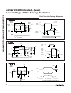
Pin Description
10
0.0001
-60 -20-40 20 60 10080
POWER-SUPPLY CURRENT
vs. TEMPERATURE
0.001
0.01
0.1
1
MAX4551-10
TEMPERATURE (°C)
I+, I- (nA)
040
I-
I+
TOTAL HARMONIC DISTORTION
vs. FREQUENCY
MAX4551-11
FREQUENCY (Hz)
THD (%)
1
0.001
0.01
0.1
1 1k 10k 100k10 100 2M
V+ = +5V
V- = -5V
600Ω IN and OUT
100m 500m
-100
-90
-80
-70
-60
-40
-50
-30
-20
0
-10
100k 1m 10m
FREQUENCY RESPONSE
MAX4551-12
FREQUENCY (Hz)
LOSS (dB)
INSERTION LOSS
OFF-ISOLATION
ON-PHASE
50Ω IN/OUT
_____________________________Typical Operating Characteristics (continued)
(V+ = +5V, V- = -5V, GND = 0, T
A
= +25°C, unless otherwise noted.)
NAME FUNCTION
1, 16, 9, 8 IN1–IN4 Logic-Control Digital Inputs
2, 15, 10, 7 COM1–COM4 Analog Switch Common* Terminals
PIN
3, 14, 11, 6 NC1–NC4 Analog Switch Normally Closed Terminals
4 V-
Negative Analog Supply-Voltage Input. Connect to GND for single-
supply operation.
1, 16, 9, 8
2, 15, 10, 7
—
13 V+
Positive Analog and Digital Supply Voltage Input. Internally con-
nected to substrate.
12 N.C. No Connection. Not internally connected.
—
4
13
12
5
1, 16, 9, 8
2, 15, 10, 7
NO1–NO4
—
4
13
12
5
MAX4551 MAX4552 MAX4553
5 GND
Ground. Connect to digital ground. (Analog signals have no ground
reference; they are limited to V+ and V-.)
Analog Switch Normally Open Terminals3, 14, 11, 6 —
— NO1, NO4 Analog Switch Normally Open Terminals— 3, 6
— NC2, NC3 Analog Switch Normally Closed Terminals— 14, 11
*NO_ (or NC_) and COM_ pins are identical and interchangeable. Either may be considered as an input or output; signals pass
equally well in either direction.