
Datasheet


MAX4533
Quad, Rail-to-Rail, Fault-Protected,
SPDT Analog Switch
8 _______________________________________________________________________________________
0
-100
0.01 0.1 1 10 100 1000
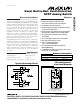
FREQUENCY RESPONSE
(DUAL SUPPLIES)
-80
-90
-70
MAX4533 toc14a
FREQUENCY (MHz)
RESPONSE (dB)
-60
-50
-40
-30
-10
-20
BANDWIDTH
V+ = +15V
V- = -15V
CROSSTALK
OFF ISOLATION
Typical Operating Characteristics (continued)
(V+ = +15V, V- = -15V, T
A
= +25°C, unless otherwise noted.)
0
-100
0.01 0.1 1 10 100 1000
FREQUENCY RESPONSE
(SINGLE SUPPLY)
-80
-90
-70
MAX4533 toc14b
FREQUENCY (MHz)
RESPONSE (dB)
-60
-50
-40
-30
-10
-20
BANDWIDTH
V+ = +12V
V- = 0
CROSSTALK
OFF ISOLATION
Pin Description
Detailed Description
The MAX4533 is a fault-protected analog switch with
special operation and construction. Traditional fault-pro-
tected switches are constructed using three-series
CMOS devices. This combination produces good fault
protection but fairly high on-resistance when the signals
are within about 3V of each supply rail. These series
devices are not capable of handling signals up to the
power-supply rails.
The MAX4533 differs considerably from traditional fault-
protected switches, with three advantages. First, it is
constructed with two parallel FETs, allowing very low
on-resistance when the switch is on. Second, they allow
signals on the NC_ or NO_ pins that are within or slightly
beyond the supply rails to be passed through the switch
to the COM_ terminal, allowing rail-to-rail signal opera-
tion. Third, when a signal on NC_ or NO_ exceeds the
supply rails by about 150mV (a fault condition), the volt-
age on COM_ is limited to the appropriate polarity sup-
ply voltage. Operation is identical for both fault
polarities. The fault-protection extends to ±25V with
power on and ±40V with power off.
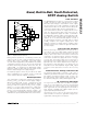
The MAX4533 has a parallel N-channel and P-channel
MOSFET switch configuration with input voltage sensors.
The simplified internal structure is shown in Figure 1. The
parallel N1 and P1 MOSFETs form the switch element.
N3 and P3 are sensor elements to sample the input volt-
age and compare it against the power-supply rails.
NAME FUNCTION
1, 10, 11, 20 IN1, IN2, IN3, IN4 Logic Control Digital Inputs
PIN
2, 9, 12, 19 NO1, NO2, NO3, NO4 Normally Open Inputs*
3, 8, 13, 18 COM1, COM2, COM3, COM4 Analog Switch Common Outputs*
4, 7, 14, 17 NC1, NC2, NC3, NC4 Normally Closed Inputs*
5 V- Negative Analog Supply Voltage Input
6 GND Digital Ground
15 N.C. No Connection. Not internally connected.
16 V+ Positive Analog and Digital Supply-Voltage Input
*When the voltage on NO_ or NC_ does not exceed V+ or V-, NO_ (or NC_) and COM_ pins are bidirectional.