
Datasheet


MAX4447/MAX4448/MAX4449
6500V/µs, Wideband, High-Output-Current, Single-
Ended-to-Differential Line Drivers with Enable
10 ______________________________________________________________________________________
Detailed Description
The MAX4447/MAX4448/MAX4449 single-ended-to-dif-
ferential converters are capable of transmitting high-
speed signals such as T1 or xDSL over twisted-pair
cable. Excellent gain and phase characteristics, along
with low distortion, make these devices suitable for
video and RF signal processing and transmission.
These converters can be interfaced directly to some of
Maxim’s wireless products, such as the MAX2450/
MAX2451.
The MAX4447/MAX4448/MAX4449 offer wide small-sig-
nal bandwidths of 430MHz, 330MHz, and 400MHz,
respectively. Internally trimmed resistors minimize gain
errors to under 2% over the full output range. Other fea-
tures include a high slew rate up to 6500V/µs and high
output current (130mA), which allow these amplifiers to
be used in numerous high-speed communications
applications.
Applications Information
Grounding and Bypassing
Use high-frequency design techniques when designing
the PC board for the MAX4447/MAX4448/MAX4449:
• Use a multilayer board with one layer dedicated as
the ground plane.
• Do not wire-wrap or use breadboards, due to high
inductance.
• Avoid IC sockets, due to high parasitic capacitance
and inductance.
• Bypass supplies with 0.1µF. Use surface-mount
capacitors to minimize lead inductance.
• Keep signal lines as short and straight as possible.
Do not make 90° turns; round all corners. Do not
cross signals if possible.
• Ensure that the ground plane is free from voids.
Output Short-Circuit Protection
Output short-circuit protection typically limits the cur-
rent to 140mA when shorted to GND, thereby keeping
the power dissipation under the absolute maximum
power dissipating rating. However, when shorted to
either supply, the short-circuit current can be signifi-
cantly higher and cause damage to the device.
Low-Power Enable Mode
The MAX4447/MAX4448/MAX4449 are disabled when
EN goes low. This reduces supply current to only
3.2mA and places the outputs into a higher impedance.
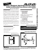
MAX4448
MAX4449
V
EE
V
CC
R
GAIN
RG
IN
OUT+
A
VCL
= 2 ( 1 + )
OUT-
300
R
GAIN
INPUT
Figure 1. Setting the Amplifier Gain
MAX4447
MAX4448
MAX4449
R
GAIN
RG
IN
OUT+
C
LOAD
R
ISO
R
ISO
OUT-
C
LOAD
V
CC
V
EE
INPUT
Figure 2. Using an Isolation Resistor for High Capacitive Loads