
Datasheet


MAX4271/MAX4272/MAX4273
3V to 12V Current-Limiting Hot-Swap Controllers
with Autoretry, DualSpeed/BiLevel Fault Protection
______________________________________________________________________________________ 19
MOSFET with a duty cycle equal to t
ON/
t
RETRY
and with
a current equal to I
FAST,SET
. Therefore, particular care
has to be taken when choosing between immediate
retry and board space needed to manage the power
dissipation capabilities of the MOSFET (see Thermal
Considerations). The duty cycle is fixed to 1/32 for the
MAX4272, but can be varied in the MAX4273 by choos-
ing CTIM and C
TON
independently.
Additional External Gate Capacitance (CEXT)
An external gate capacitance can be connected at
GATE. This increases the time required to enhance the
MOSFET and further limits the output rise time. In the
MAX4271/MAX4272, connect the external capacitor
between GATE and GND. In the MAX4273, the external
capacitor can be connected between GATE and CEXT
or GND. If the capacitor is connected to CEXT, it is dis-
charged to ground during a slow comparator fault but it
is left floating during a fast comparator fault; this allows
the device to turn off the external MOSFET faster during
critical faults. (CEXT is biased at V
IN
; therefore, use a
nonpolarized capacitor). Capacitance connected from
GATE to CEXT does little to decrease the regulated cur-
rent ripple. Add a small capacitor (5nF) from GATE to
GND. See the charging and discharging time vs. C
GATE
graphs in the Typical Operating Characteristics.
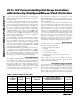
Slow Comparator Response Time (CSPD)
The slow comparator threshold is set at 50mV, and its
response time is determined by the external capacitor
connected to CSPD (Figure 10).
A minimum response time of 20µs (typ) is achieved by
leaving this pin floating. This time is determined inter-
nally and is not affected by stray capacitance at CSPD
(up to 100pF).
Set the slow comparator response time to be longer
than the normal operation load transients (see Slow
Comparator).
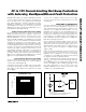
ON and Reset Comparators
The ON comparator controls the ON/OFF function of
these devices. The ON comparator is a precision volt-
age comparator that can be used for temperature moni-
toring or as an additional UVLO (Figure 11). The
MAX4273 also features an uncommitted delayed com-
parator. This comparator can be used for voltage moni-
toring, power sequencing, or for generating a power-on
reset signal for on-card microprocessors (Figure 12).
Both comparator threshold voltages are set at V
REF
/2 =
0.6V with a 3mV (typ) hysteresis.
The uncommitted comparator OUTC output is an open-
drain output, and it is asserted low when its input volt-
age (INC) is below the threshold voltage. It goes into a
high-impedance state 150ms after the voltage has risen
above the threshold. The delay for negative-going
edges is 10µs.
Figure 13 shows the MAX4273 used to monitor precise-
ly the temperature of an external device such as the
MOSFET. This configuration uses the uncommitted
comparator to set the UVLO at a higher level by running
its output into the ON comparator’s input.
The ON comparator initiates startup when its input volt-
age (V
ON
) rises above the threshold voltage and turns
off the MOSFET when the voltage falls below the thresh-
old. The propagation delay is 10µs going high or low.
The ON comparator is also used to reset the
MAX4271/MAX4273 (when CTIM = V
IN
) after a fault
condition (see Latched/Autoretry).
Figure 10. Slow Comparator Response Time vs. CSPD
1000
0.01 0.1 1 10 100 1000
100
10
1
0.1
0.01
SLOW COMPARATOR
RESPONSE TIME vs. CSPD
CSPD (nF)
RESPONSE TIME (ms)
t
CSPD
(ms) = 0.2 x CSPD (nF)
Figure 11. Temperature Monitoring and Protection
LOGIC
CONTROL
V
REF
R2
ON
NTC
R1 = R2
✕
(V
REF
/ O.6 - 1)
R2 = VALUE OF THE NTC RESISTOR AT THE LIMIT TEMPERATURE
V
REF
= ANY REFERENCE VOLTAGE AVAILABLE OR V
IN
0.6V
R1
MAX4271
MAX4272
MAX4273