
Datasheet


MAX4122–MAX4129
Single/Dual/Quad, Wide-Bandwidth, Low-Power,
Single-Supply Rail-to-Rail I/O Op Amps
______________________________________________________________________________________ 13
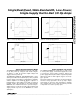
V
CC
TIME (5µs/div)
VOLTAGE (1V/div)
OUT
Figure 11. Power-Up Output Voltage
SHDN
(1V/div)
TIME (2µs/div)
OUT
(0.5V/div)
V
CC
= 2.7V
R
L
= 10kΩ
Figure 13. Shutdown Output Voltage
V
CC
(1V/div)
TIME (5µs/div)
I
CC
(500µA/div)
Figure 12. Power-Up Supply Current
SHDN
(1V/div)
TIME (2µs/div)
I
CC
(500µA/div)
V
CC
= 2.7V
Figure 14. Shutdown Enable/Disable Supply Current
Power-Up and Shutdown Mode
The MAX4122–MAX4129 amplifiers typically settle with-
in 1µs after power-up. Using the test circuit of Figure
10, Figures 11 and 12 show the output voltage and
supply current on power-up.
The MAX4123, MAX4125, and MAX4127 have a shut-
down option. When the shutdown pin (SHDN) is pulled
low, the supply current drops below 25µA per amplifier
and the amplifiers are disabled with the outputs in a
high-impedance state. Pulling SHDN high or leaving it
floating enables the amplifier. In the dual-amplifier
MAX4129, the shutdown functions operate indepen-
dently. Figures 13 and 14 show the output voltage and
supply current responses of the MAX4123 to a shut-
down pulse.
Power Supplies and Layout
The MAX4122–MAX4129 operate from a single +2.7V
to +6.5V power supply, or from dual supplies of ±1.35V
to ±3.25V. For single-supply operation, bypass the
power supply with a 0.1µF ceramic capacitor in parallel
with at least 1µF. For dual supplies, bypass each sup-
ply to ground.
Good layout improves performance by decreasing the
amount of stray capacitance at the op amp’s inputs
and outputs. To decrease stray capacitance, minimize
trace lengths and resistor leads by placing external
components close to the op amp’s pins.