
Datasheet


MAX3942
10Gbps Modulator Driver
_______________________________________________________________________________________ 9
Interface Schematics
Figures 5 and 6 show simplified input and output cir-
cuits of the MAX3942 modulator driver.
To minimize inductance, keep the connections from
OUT, GND, and V
EE
as short as possible. This is crucial
for optimal performance.
Laser Safety and IEC 825
Using the MAX3942 EAM driver alone does not ensure
that a transmitter design is compliant with IEC 825. The
entire transmitter circuit and component selections must
be considered. Each customer must determine the level
of fault tolerance required by their application, recogniz-
ing that Maxim products are not designed or authorized
for use as components in systems intended for surgical
implant into the body, for applications intended to sup-
port or sustain life, or for any other application where the
failure of a Maxim product could create a situation where
personal injury or death may occur.
Figure 5. Simplified Input Circuit
MAX3942
DATA+/CLK+
50Ω 50Ω
GND
V
EE
DATA-/CLK-
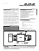
Figure 4. Functional Diagram
50Ω 50Ω
50Ω 50Ω
50Ω
50Ω
CLK+
CLK-
DATA-
DATA+
0
1
MUX
DQ
PWC
POLARITY
I
MOD
V
EE
V
EE
V
MODSET
MODENRTEN PLRT
OUT-
OUT+
-
+
PWC+ PWC-
V
EE
50Ω 50Ω
2kΩ
V
EE
MAX3942
MODSET