
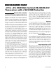
Datasheet


Transformer Selection
The MXL1535E is a pin-for-pin compatible upgrade of
the LTC1535, making any transformer designed for that
device suitable for the MXL1535E (see Table 4). These
transformers all have a turns ratio of about 1:1.3CT.
The MAX3535E can operate with any of the transformers
listed in Table 4, in addition to smaller, thinner transform-
ers designed for the MAX845 and MAX253. The 420kHz
transformer driver operates with single primary and cen-
ter-tapped secondary transformers. When selecting a
transformer, do not exceed its ET product, the product of
the maximum primary voltage and half the highest period
of oscillation (lowest oscillating frequency). This ensures
that the transformer does not enter saturation. Calculate
the minimum ET product for the transformer primary as:
ET = V
MAX
/ (2 x f
MIN
)
where, V
MAX
is the worst-case maximum supply voltage,
and f
MIN
is the minimum frequency at that supply voltage.
Using +5.5V and 290kHz gives a required minimum ET
+3V to +5V, 2500V
RMS
Isolated RS-485/RS-422
Transceivers with ±15kV ESD Protection
TGM-250
1/2
BAT54C
TRANSFORMER
DRIVER
BARRIER
TRANSCEIVER
ISOLATION BARRIER
BARRIER
TRANSCEIVER
1/2
BAT54C
VOLTAGE
REGULATOR
GND2
+5V
DRIVER
RECEIVER
A
B
Y
Z
Y
Z
SLO
RO2
ST1
RO1
RO
RE
DE
DI
DI
GND1
ST2
V
CC2
V
CC1
V
CC2
0.1μF
0.1μF
CONTROL GROUND
RS-422 GROUND
10μF
10μF
MAX3535E
MXL1535E
MAX488
R
D
A
B
120Ω
120Ω
RD
DR
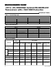
Figure 12. Using the MAX3535E/MXL1535E as an RS-422 Line Repeater
V
CC1
R
OH
R
OH
R
OL
R
OL
TRANSFORMER DRIVER OUTPUT STAGE
TRANSFORMER
PRIMARY
GND1
ST1 ST2
Figure 13. Transformer Driver Output Stage
MAX3535E/MXL1535E
20
Maxim Integrated
MAX3535E/MXL1535E